STM32 Introduction
What are STM32 Microcontrollers?
STM32 is a family of 32-bit microcontrollers developed by STMicroelectronics based on the ARM Cortex-M processor architecture. Introduced in 2007, these microcontrollers have gained immense popularity in the embedded systems world thanks to their powerful features, flexibility, and competitive pricing.
Why Choose STM32?
New to embedded systems and wondering why choose STM32 over simpler options like Arduino? Consider these reasons:
- Performance: STM32 outperforms 8-bit microcontrollers used in Arduino boards.
- Cost-effectiveness: Excellent features at competitive prices.
- Variety: Hundreds of options with different capabilities for specific applications.
- Rich peripheral set: Built-in ADCs, DACs, timers, communication interfaces, and more.
- Industry relevance: Highly valued skills in the embedded industry.
- Scalability: Grows with your project complexity without platform changes.
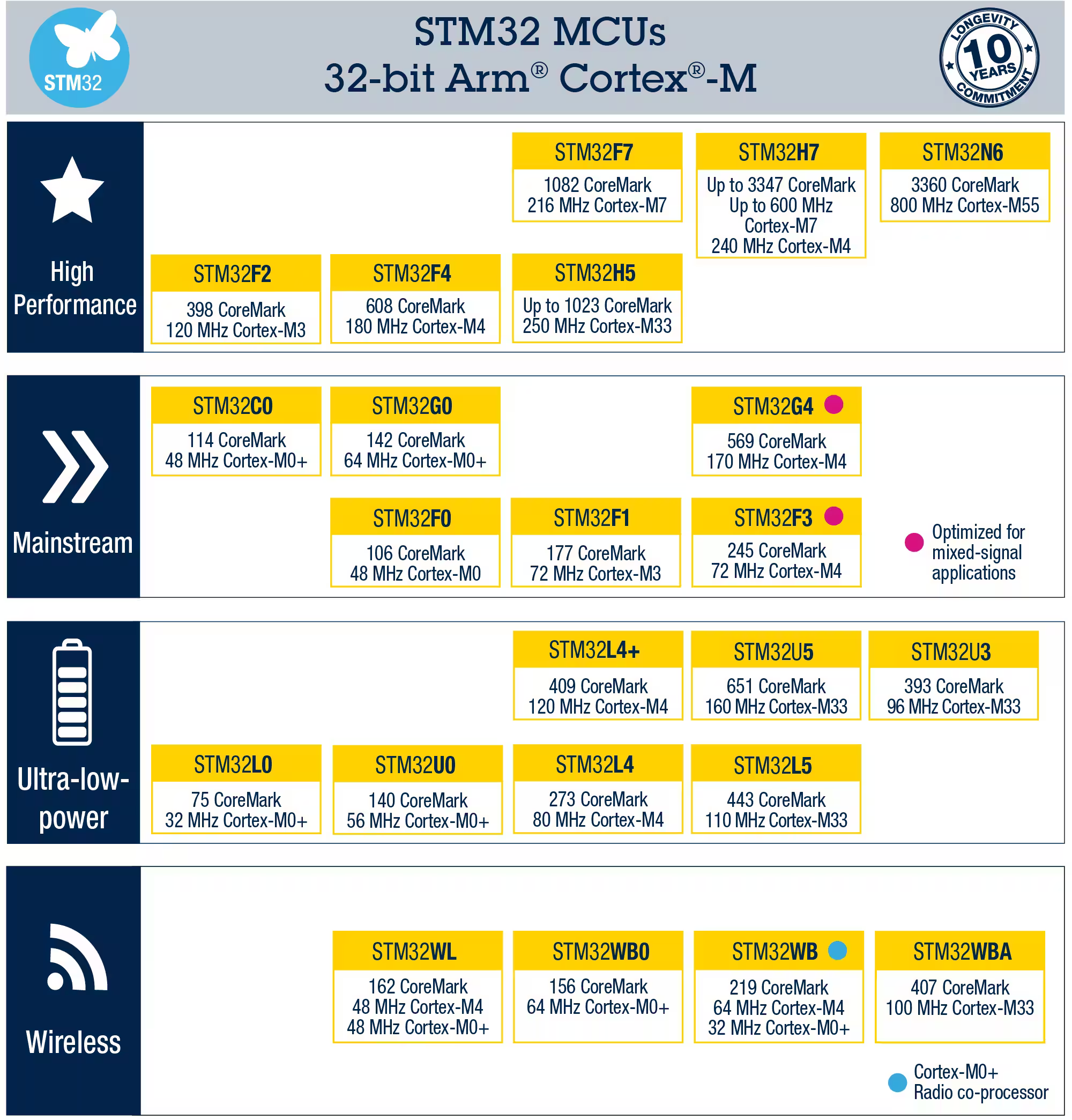
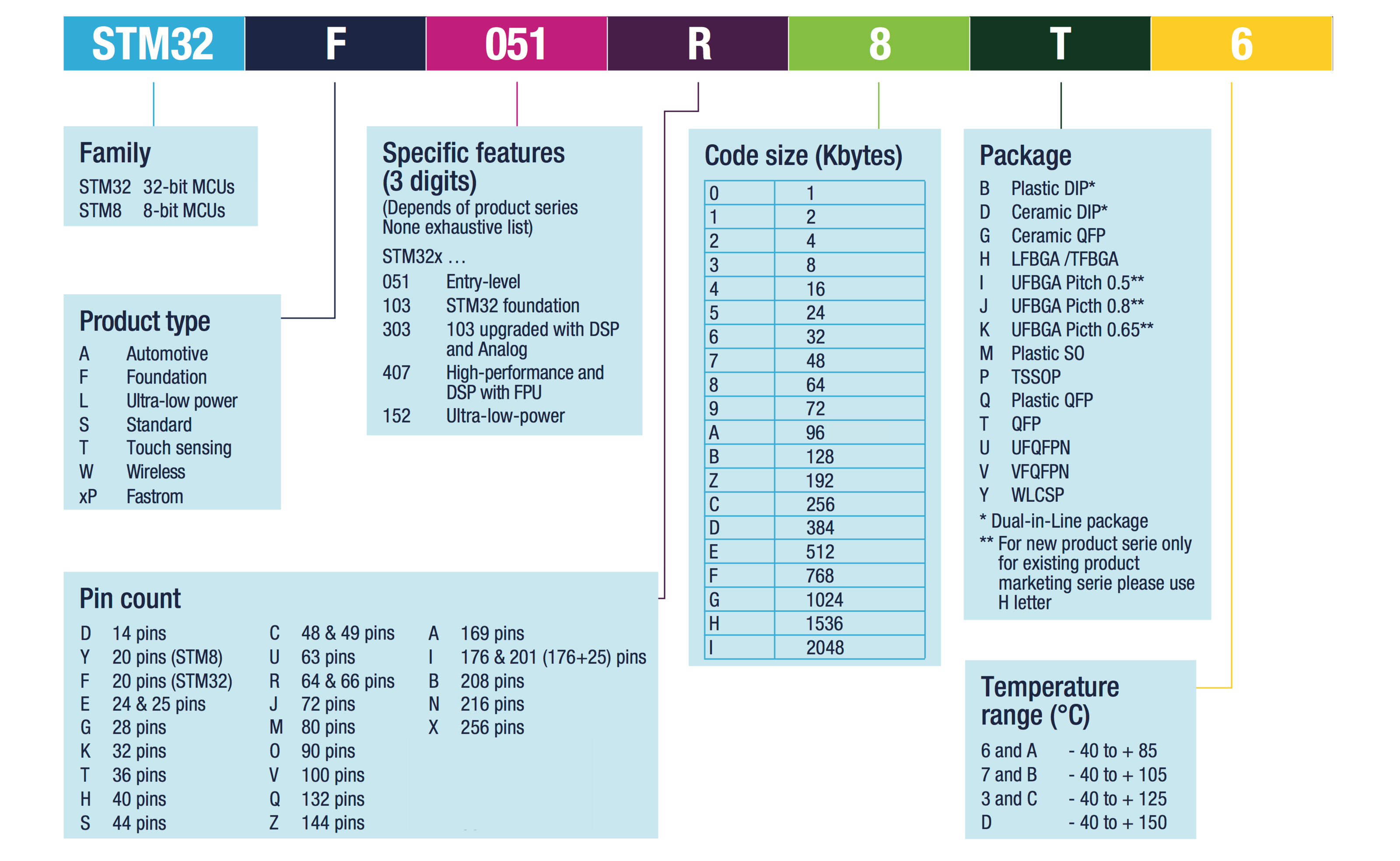
STM32 Family Overview
Key STM32 Concepts
GPIO (General Purpose Input/Output)
GPIO pins are digital pins that can be configured as either inputs or outputs.
static void MX_GPIO_Init(void)
{
  GPIO_InitTypeDef GPIO_InitStruct = {0};

  /* GPIO Ports Clock Enable */
  __HAL_RCC_GPIOA_CLK_ENABLE();

  /* Configure GPIO pin Output Level */
  HAL_GPIO_WritePin(GPIOA, GPIO_PIN_5, GPIO_PIN_RESET);

  /* Configure GPIO pin : PA5 (LED) */
  GPIO_InitStruct.Pin = GPIO_PIN_5;
  GPIO_InitStruct.Mode = GPIO_MODE_OUTPUT_PP;
  GPIO_InitStruct.Pull = GPIO_NOPULL;
  GPIO_InitStruct.Speed = GPIO_SPEED_FREQ_LOW;
  HAL_GPIO_Init(GPIOA, &GPIO_InitStruct);
}
Or direct register manipulation offers the best performance and smallest code size but requires deep knowledge of the hardware.
STM32 Introduction/General-purpose I Os (GPIO)
/*
		GPIOA_MODER = 01
		GPIOA_OTYPER = 0
		GPIOA_OSPEEDR = 00
		GPIOA_PUPDR = 00
*/

#define GREEN_LED_BIT 5

int main() {
  //In Run mode, the HCLKx and PCLKx for individual peripherals and memories can be
  //stopped at any time to reduce power consumption.
  RCC->AHB1ENR |= RCC_AHB1ENR_GPIOAEN;
  // Set PA5 low (reset)
  GPIOA->BSRR = (1u << (GREEN_LED_BIT + 16));

  // Set PA5 as output (MODER5 = 0b01)
  GPIOA->MODER &= ~(2u << (GREEN_LED_BIT * 2)); // Clear bits 10
  GPIOA->MODER |=  (1u << (GREEN_LED_BIT * 2)); // Set bit 10

  // Set PA5 as push-pull (OTYPER5 = 0)
  GPIOA->OTYPER &= ~(1u << GREEN_LED_BIT);

  // Set PA5 speed to low (OSPEEDR5 = 0b00)
  GPIOA->OSPEEDR &= ~(3u << (GREEN_LED_BIT * 2)); // Clear bits 10 and 11

  // Set PA5 no pull-up/pull-down (PUPDR5 = 0b00)
  GPIOA->PUPDR &= ~(3u << (GREEN_LED_BIT * 2)); // Clear bits 10 and 11


 // just togelling the led at your cpu clock speed for fun
  GPIOA->ODR ^= (1u << 5);
  GPIOA->ODR ^= (1u << 5);
  GPIOA->ODR ^= (1u << 5);
  GPIOA->ODR ^= (1u << 5);
 }
Clock System
The main clock sources are:
- HSI: High-Speed Internal RC oscillator (typically 8/16 MHz)
- HSE: High-Speed External crystal or clock (4-26 MHz)
- LSI: Low-Speed Internal RC oscillator (32-40 kHz)
- LSE: Low-Speed External crystal (32.768 kHz)
- PLL: Phase-Locked Loop for frequency multiplication
example of initialization of the system clock using the system core and sysTick, in cmsis
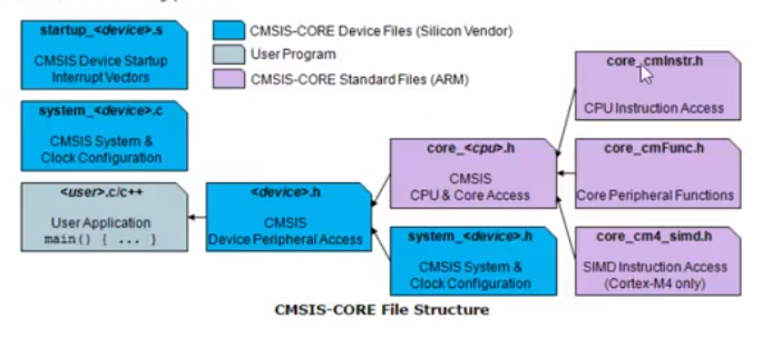
💡 ### CMSIS (Cortex Microcontroller Software Interface Standard)
CMSIS is a hardware abstraction layer for ARM Cortex-M microcontrollers that provides:
- Standardized interface to the Cortex-M processor core and peripherals
- Vendor-independent hardware abstraction layer
- Consistent device support across different microcontroller vendors
#include <stdint.h>
#include "stm32f4xx.h"
#define GREEN_LED_BIT 5

uint32_t tick;
uint32_t _tick;

void Clcok_init(void);
void DelaySec(uint32_t seconds);

int main(void)
{
	Clcok_init();

	RCC->AHB1ENR |= RCC_AHB1ENR_GPIOAEN;
	// Set PA5 low (reset)
	GPIOA->BSRR = (1u << (GREEN_LED_BIT + 16)); // Reset PA5

	// Set PA5 as output (MODER5 = 0b01)
	GPIOA->MODER &= ~(3u << (GREEN_LED_BIT * 2)); // Clear bits 10 and 11
	GPIOA->MODER |=  (1u << (GREEN_LED_BIT * 2)); // Set bit 10

	while (1)
	{
	  GPIOA->ODR ^= (1u << 5);
	  DelaySec(1);
	}

}

void Clcok_init(void)
{
	// Update 'SystemCoreClock' variable according to Clock Register Values.
	SystemCoreClockUpdate();
	// Initializes the System Timer and its interrupt, and starts the System Tick Timer.
	// the interrrupt will be called every 1ms (that is why it is deviced by 1000)
	SysTick_Config(SystemCoreClock/1000);
	// enable all interrupts. (because the systick uses the SysTick_Handler
	//  function as a handler for the interrup that is called evry 1ms in our case)
	__enable_irq();

	return;
}

// definetion of the interrupt
void SysTick_Handler(void)
{
	++tick;
}

uint32_t getTick(void)
{
	// get tick is a critical fucntion and can't be interrupted
	__disable_irq();
	_tick = tick;
	__enable_irq();

	return _tick;
}

void DelaySec(uint32_t seconds)
{
	seconds *= 1000;
	uint32_t temp = getTick();
	while ((getTick() - temp) < seconds) {}

	return;
}
Interrupts
STM32 Introduction/Set An ISR to execute when a GPIO is set high STM32
Nested Vectored Interrupt Controller (NVIC):
The NVIC manages interrupts with minimal latency and maximum configurability:
- Priority-based interrupt handling
- Nested interrupt support
- Vector table for fast interrupt response
- Configurable priority levels
- Non-maskable interrupt (NMI) support
- Dedicated SysTick timer for operating system timing
Development Approaches
1. HAL (Hardware Abstraction Layer)
HAL
provides a high-level, portable API that simplifies microcontroller
programming. It's beginner-friendly but can be less efficient.
// HAL example: Reading an ADC value
HAL_ADC_Start(&hadc1);
HAL_ADC_PollForConversion(&hadc1, 100);
uint16_t adcValue = HAL_ADC_GetValue(&hadc1);
2. LL (Low-Layer)
The LL library offers better performance than HAL but requires more understanding of the hardware.
// LL example: Setting up a GPIO pin
LL_GPIO_SetPinMode(GPIOA, LL_GPIO_PIN_5, LL_GPIO_MODE_OUTPUT);
LL_GPIO_SetOutputPin(GPIOA, LL_GPIO_PIN_5);
3. Register-Level Programming
Direct register manipulation offers the best performance and smallest code size but requires deep knowledge of the hardware.
// Register-level example: Toggling an LED
GPIOA->ODR ^= (1 << 5);
As a beginner, start with HAL and gradually explore LL and register-level programming as you become more comfortable.
CMSIS
CMSIS (Cortex Microcontroller Software Interface Standard) is a vendor-independent hardware abstraction layer for ARM Cortex-M microcontrollers. Developed by ARM, CMSIS provides standardized APIs, device header files, and startup code, making it easier to develop and port embedded software across different ARM Cortex-M devices. It includes components for core access, device peripheral access, DSP libraries, RTOS interfaces, and more.
STM32 Introduction/Setup a CMSIS only project in cubeIDE (no HAL)