UART
UART : Protocol Summary
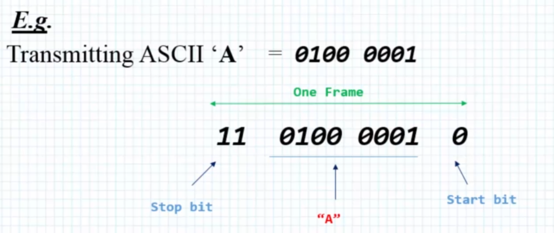
In asynchronous transmission, each byte (character) is packed between start and stop bits.
- Start bit is always 1 bit, the value of the start bit is always 0
- Stop bit can be 1 or 2 bits, the value of the stop bit is always 1
E.g.
Transmitting ASCII 'A' = 0100 0001
One Frame:
11 0100 0001 0
Stop bit "A" Start bit
configuration parameters
- Baudrate: Connection speed expressed in bits per second
- Stop Bit :Number of stop bits transmitted, can be one or two
- Parity: Indicates the parity mode, whether odd or even. Used for error checking.
- Mode: Specifies whether RX or TX mode is enabled or disabled.
- Word Length: Specifies the number of data bits transmitted or received. Can be 8-bits or 9-bits.
- Hardware Flow Control: Specifies whether Hardware Flow Control is enabled
or disabled.
#include "stm32f4xx.h"

#define GPIOAEN      (1U<<0)
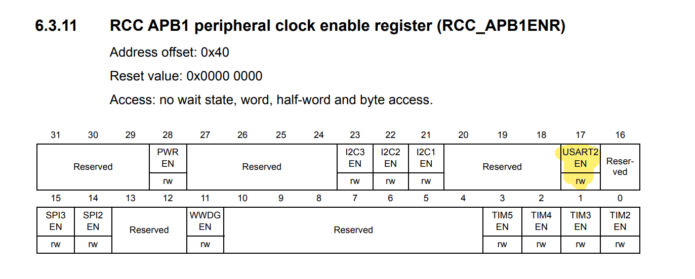
#define UART2EN      (1U<<17)

#define CR1_TE       (1U<<3)
#define CR1_UE       (1U<<13)

#define SYS_FREQ     16000000
#define APB1_CLK     SYS_FREQ
#define UART_BAUDRATE 115200

static void uart_set_baudrate(USART_TypeDef *USARTx, uint32_t PeriphClk, uint32_t BaudRate);
static uint16_t compute_uart_bd(uint32_t PeriphClk, uint32_t BaudRate);

int main(void)
{
    while(1)
    {
    }
}

void uar2_tx_init(void)
{
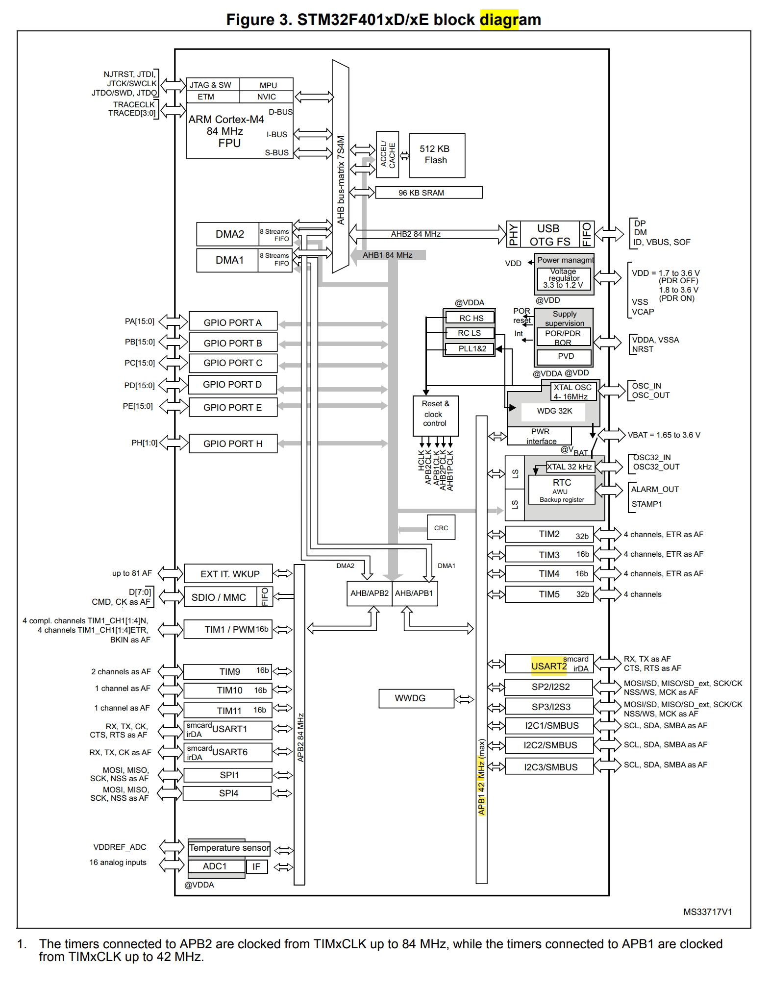
    /**************Configure uart gpio pin***************/
    /*Enable clock access to gpioa */
    RCC->AHB1ENR |= GPIOAEN;

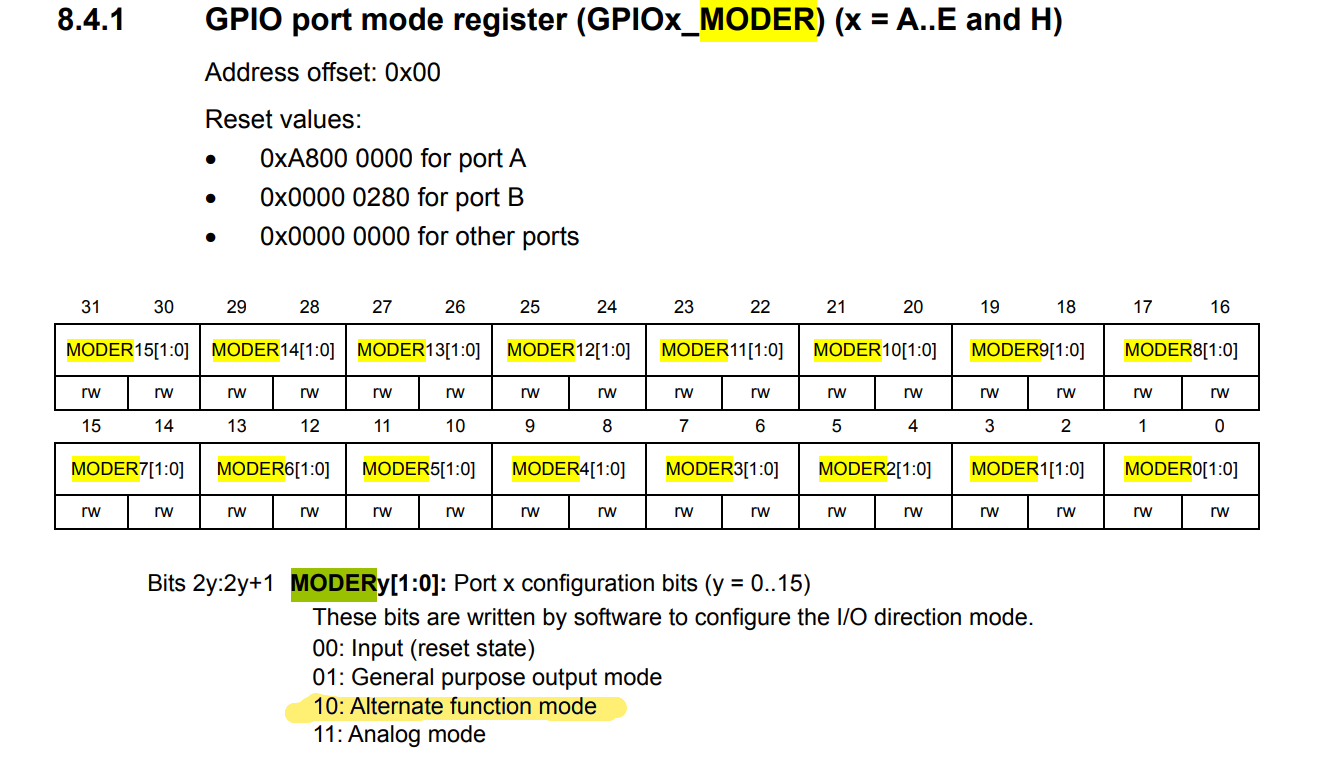
    /*Set PA2 mode to alternate function mode*/
    GPIOA->MODER &= ~(1U<<4);
    GPIOA->MODER |= (1U<<5);

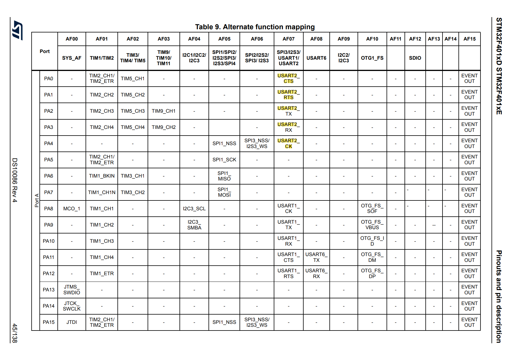
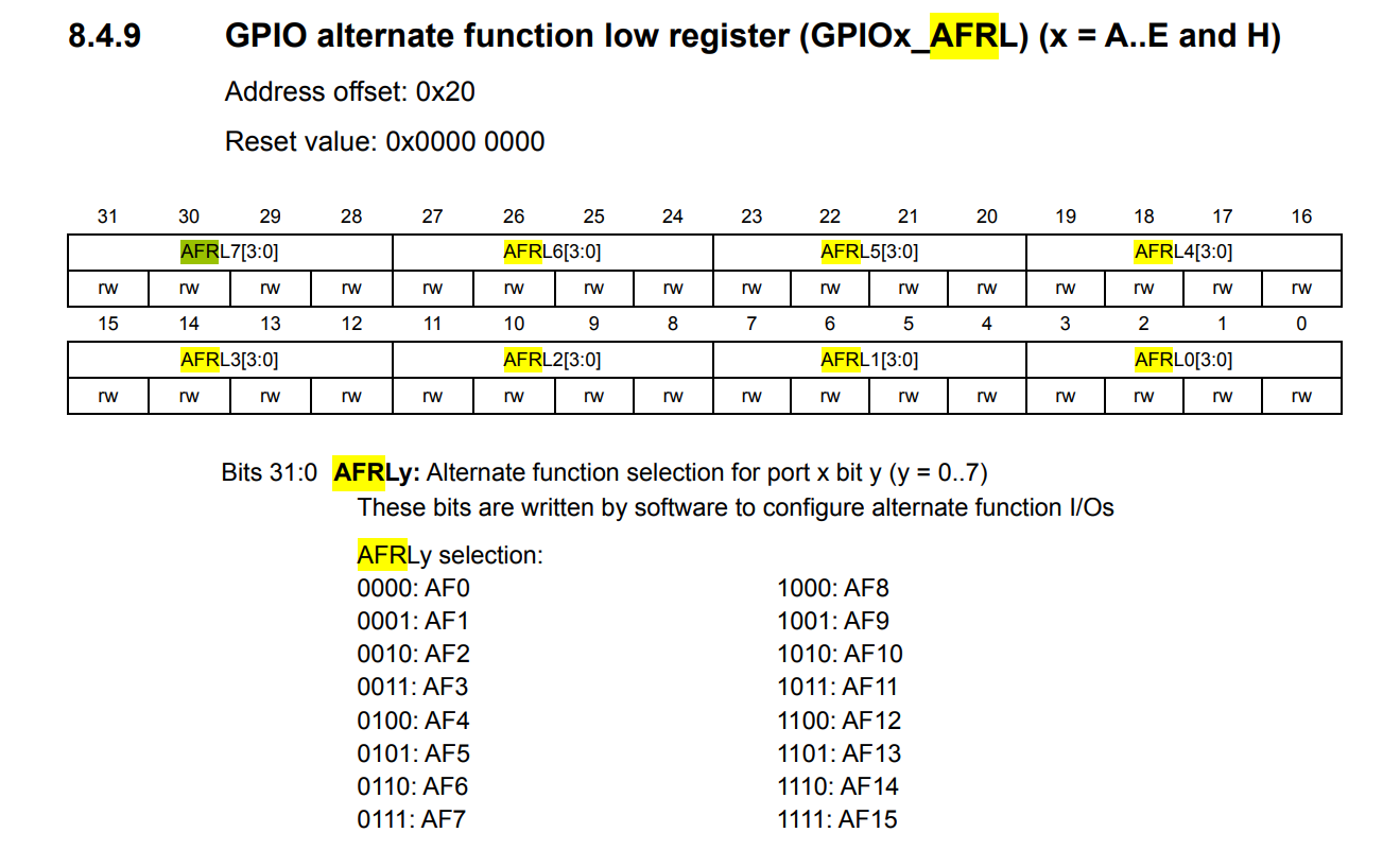
    /*Set PA2 alternate function type to UART_TX (AF07)*/
    GPIOA->AFR[0] |= (1U<<8);
    GPIOA->AFR[0] |= (1U<<9);
    GPIOA->AFR[0] |= (1U<<10);
    GPIOA->AFR[0] &= ~(1U<<11);

    /**************Configure uart module***************/
    /*Enable clock access to uart2 */
    RCC->APB1ENR |= UART2EN;

    /*Configure baudrate*/
    uart_set_baudrate(USART2, APB1_CLK, UART_BAUDRATE);

    /*Configure the transfer direction*/
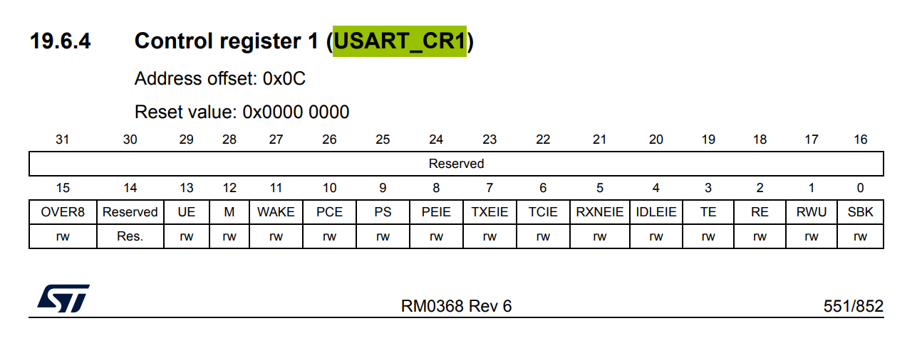
    USART2->CR1 = CR1_TE;

    /*Enable uart module*/
    USART2->CR1 |= CR1_UE;
}

static void uart_set_baudrate(USART_TypeDef *USARTx, uint32_t PeriphClk, uint32_t BaudRate)
{
    USARTx->BRR = compute_uart_bd(PeriphClk, BaudRate);
}

static uint16_t compute_uart_bd(uint32_t PeriphClk, uint32_t BaudRate)
{
    return (PeriphClk + (BaudRate/2U))/BaudRate;
}
#include "stm32f4xx.h"
#include "stdio.h"

#define GPIOAEN      (1U<<0)
#define UART2EN      (1U<<17)

#define CR1_TE       (1U<<3)
#define CR1_UE       (1U<<13)
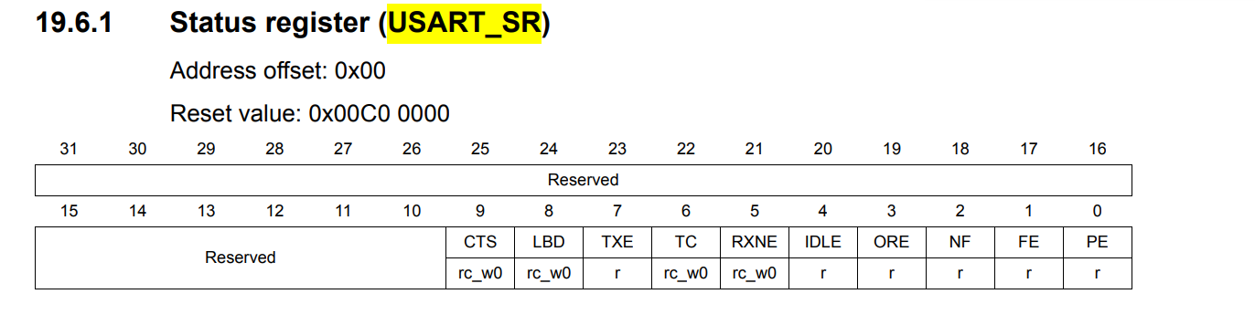
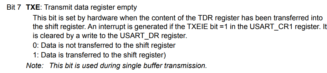
#define SR_TXE 	     (1U<<7)

#define SYS_FREQ     16000000
#define APB1_CLK     SYS_FREQ
#define UART_BAUDRATE 115200

static void uart_set_baudrate(USART_TypeDef *USARTx, uint32_t PeriphClk, uint32_t BaudRate);
static uint16_t compute_uart_bd(uint32_t PeriphClk, uint32_t BaudRate);

void uart2_tx_init(void);
void uart2_write(int ch);

int __io_putchar(int ch)
{
    uart2_write(ch);
    return ch;
}

int main(void)
{
    uart2_tx_init();

    while(1)
    {
        printf("Hello from STM32F4........\n\r");
    }
}

void uart2_tx_init(void)
{
    /**************Configure uart gpio pin***************/
    /*Enable clock access to gpioa */
    RCC->AHB1ENR |= GPIOAEN;

    /*Set PA2 mode to alternate function mode*/
    GPIOA->MODER &= ~(1U<<4);
    GPIOA->MODER |= (1U<<5);

    /*Set PA2 alternate function type to UART_TX (AF07)*/
    GPIOA->AFR[0] |= (1U<<8);
    GPIOA->AFR[0] |= (1U<<9);
    GPIOA->AFR[0] |= (1U<<10);
    GPIOA->AFR[0] &= ~(1U<<11);

    /**************Configure uart module***************/
    /*Enable clock access to uart2 */
    RCC->APB1ENR |= UART2EN;

    /*Configure baudrate*/
    uart_set_baudrate(USART2, APB1_CLK, UART_BAUDRATE);

    /*Configure the transfer direction*/
    USART2->CR1 = CR1_TE;

    /*Enable uart module*/
    USART2->CR1 |= CR1_UE;
}

void uart2_write(int ch)
{
    /*Make sure the transmit data register is empty*/
    while(!(USART2->SR & SR_TXE)){}

    /*Write to transmit data register*/
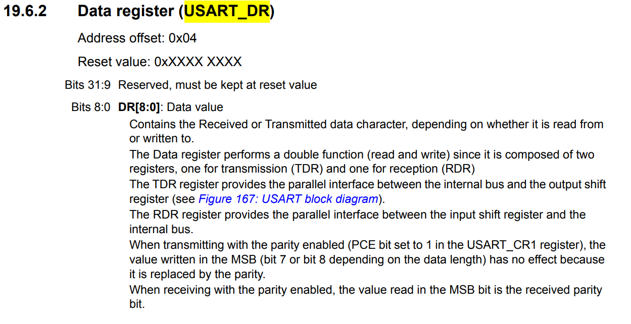
    USART2->DR = (ch & 0xFF);
}

static void uart_set_baudrate(USART_TypeDef *USARTx, uint32_t PeriphClk, uint32_t BaudRate)
{
    USARTx->BRR = compute_uart_bd(PeriphClk, BaudRate);
}

static uint16_t compute_uart_bd(uint32_t PeriphClk, uint32_t BaudRate)
{
    return (PeriphClk + (BaudRate/2U))/BaudRate;
}
RX and TX
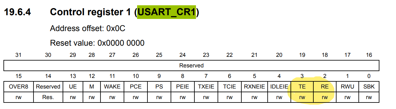
#include "stm32f4xx.h"
#include "stdio.h"

#define GPIOAEN (1U << 0)
#define UART2EN (1U << 17)

#define CR1_RE (1U << 2)
#define CR1_TE (1U << 3)
#define CR1_UE (1U << 13)
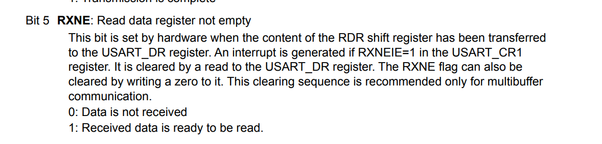
#define SR_RXNE (1U << 5)
#define SR_TXE (1U << 7)

#define SYS_FREQ 16000000
#define APB1_CLK SYS_FREQ
#define UART_BAUDRATE 115200

static void uart_set_baudrate(USART_TypeDef *USARTx, uint32_t PeriphClk, uint32_t BaudRate);
static uint16_t compute_uart_bd(uint32_t PeriphClk, uint32_t BaudRate);

void uart2_rxtx_init(void);
void uart2_write(int ch);
char uart2_read();

int __io_putchar(int ch)
{
  uart2_write(ch);
  return ch;
}

volatile char key;
int main(void)
{
  uart2_rxtx_init();
  char echo[1] = " ";

  while (1)
  {
    key = uart2_read();
    echo[0] = key;
    printf("%s", echo); // Use format string
  }
}

void uart2_rxtx_init(void)
{
  /**************Configure uart gpio pin***************/
  /*Enable clock access to gpioa */
  RCC->AHB1ENR |= GPIOAEN;

  /*Set PA2 mode to alternate function mode*/
  GPIOA->MODER &= ~(1U << 4);
  GPIOA->MODER |= (1U << 5);

  /*Set PA2 alternate function type to UART_TX (AF07)*/
  GPIOA->AFR[0] |= (1U << 8);
  GPIOA->AFR[0] |= (1U << 9);
  GPIOA->AFR[0] |= (1U << 10);
  GPIOA->AFR[0] &= ~(1U << 11);

  /*Set PA3 mode to alternate function mode*/
  GPIOA->MODER &= ~(1U << 6);
  GPIOA->MODER |= (1U << 7);

  /*Set PA3 alternate function type to UART_RX (AF07) */
  GPIOA->AFR[0] |= (1 << 12);
  GPIOA->AFR[0] |= (1 << 13);
  GPIOA->AFR[0] |= (1 << 14);
  GPIOA->AFR[0] &= ~(1 << 15);

  /**************Configure uart module***************/
  /*Enable clock access to uart2 */
  RCC->APB1ENR |= UART2EN;

  /*Configure baudrate*/
  uart_set_baudrate(USART2, APB1_CLK, UART_BAUDRATE);

  /*Configure the transfer direction*/
  USART2->CR1 = (CR1_TE | CR1_RE);

  /*Enable uart module*/
  USART2->CR1 |= CR1_UE;
}

char uart2_read()
{
  /*Make sure the receive data register is not empty*/
  while (!(USART2->SR & SR_RXNE))
  {
  }
  /*Read data*/
  return USART2->DR;
}

void uart2_write(int ch)
{
  /*Make sure the transmit data register is empty*/
  while (!(USART2->SR & SR_TXE))
  {
  }

  /*Write to transmit data register*/
  USART2->DR = (ch & 0xFF);
}

static void uart_set_baudrate(USART_TypeDef *USARTx, uint32_t PeriphClk, uint32_t BaudRate)
{
  USARTx->BRR = compute_uart_bd(PeriphClk, BaudRate);
}

static uint16_t compute_uart_bd(uint32_t PeriphClk, uint32_t BaudRate)
{
  return (PeriphClk + (BaudRate / 2U)) / BaudRate;
}
UART Interrupt
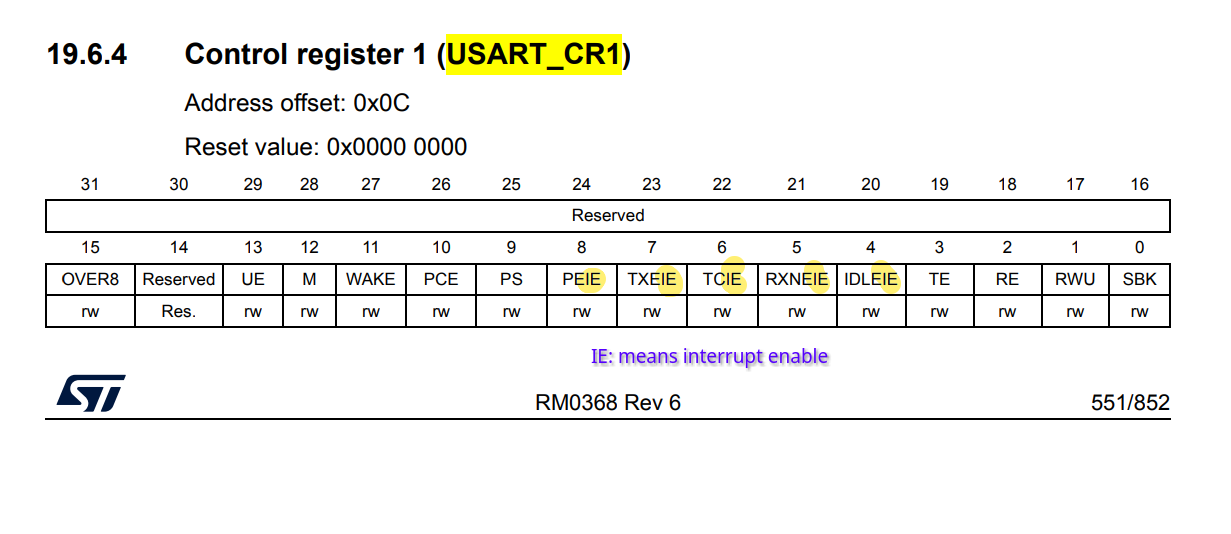
#define CR1_RXNEIE  (1U<<5)
#define CR1_TXEIE  (1U<<7)

void uart2_rx_intr_init(void)
{
  /**************Configure uart gpio pin***************/
  /*Enable clock access to gpioa */
  RCC->AHB1ENR |= GPIOAEN;

  /*Set PA2 mode to alternate function mode*/
  GPIOA->MODER &= ~(1U << 4);
  GPIOA->MODER |= (1U << 5);

  /*Set PA2 alternate function type to UART_TX (AF07)*/
  GPIOA->AFR[0] |= (1U << 8);
  GPIOA->AFR[0] |= (1U << 9);
  GPIOA->AFR[0] |= (1U << 10);
  GPIOA->AFR[0] &= ~(1U << 11);

  /*Set PA3 mode to alternate function mode*/
  GPIOA->MODER &= ~(1U << 6);
  GPIOA->MODER |= (1U << 7);

  /*Set PA3 alternate function type to UART_RX (AF07) */
  GPIOA->AFR[0] |= (1 << 12);
  GPIOA->AFR[0] |= (1 << 13);
  GPIOA->AFR[0] |= (1 << 14);
  GPIOA->AFR[0] &= ~(1 << 15);

  /**************Configure uart module***************/
  /*Enable clock access to uart2 */
  RCC->APB1ENR |= UART2EN;

  /*Configure baudrate*/
  uart_set_baudrate(USART2, APB1_CLK, UART_BAUDRATE);

  /*Configure the transfer direction*/
  USART2->CR1 = (CR1_TE | CR1_RE | CR1_RXNEIE | CR1_TXEIE);

	/* ENbale UART2 interrupt in NVIC */
	NVIC_EnableIRQ(USART2_IRQn);

  /*Enable uart module*/
  USART2->CR1 |= CR1_UE;
}

void USART2_IRQHandler(void)
{
	if (USART2->SR & SR_RXNE)
	{
		char rx = USART2->DR;
	}
}