RTC
RTC: Introduction
- A real-time clock (RTC) is a computer clock that keeps track of the current time.
- Real-time clocks (RTC) are in almost any electronic device that requires an accurate time keeping.
RTC: RTC and Backup Registers
The STM32 contains two power domains:
- Main System and Peripheral Power Domain
- Backup Power Domain
The RTC and the Independent Watchdog are located within the backup domain.
RTC: RTC and Backup Registers
Backup Registers
Memory locations that can be used to hold critical data values during the Standby mode when the main power domain is switched off.
In low power mode both the RTC and the independent watchdog can be kept running and may be used to wake up the system or to perform a chip reset.
RTC: RTC and Wakeup
- Because RTC is in the backup power domain, when the main power domain of the stm32 is put in a low power mode, the RTC will keep running.
- Through the EXTI line 17 the RTC can generate an interrupt of events on the Cortex-M NVIC to wake up the main stm32 power domain.
RTC : Backup Registers And Tamper Pin
-
The backup power domain contains registers which act as battery-backed SRAM.
The data held in these registers can be cleared by writing to the RCC backup control register.
-
An external tamper pin can be configured to be high or low during startup. During normal operation a change in logic level will trigger a tamper detect event, which will clear the backup registers.
RTC : Backup Registers And Tamper Pin
- A tamper interrupt can be enabled, which allows the application software to take defensive action if a tamper condition is detected.
RTC : Calendar
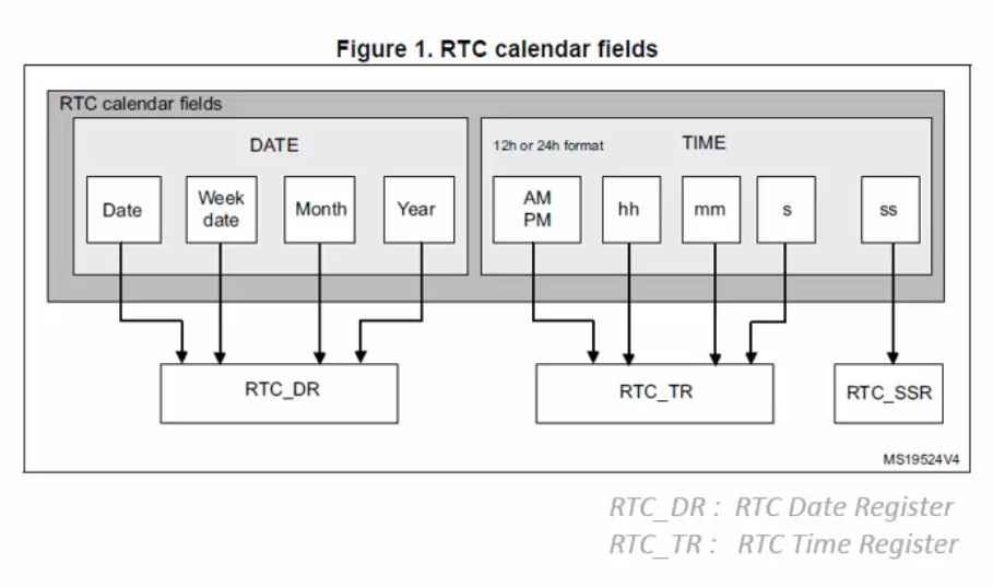
- A calendar keeps track of time in hours, minutes and seconds and date in days, weeks, months and years.
RTC : Main Features
- Calendar
- Two programmable Alarms
- Automatic Wakeup generation
- Tamper detection
- 20 backup registers
- Maskable Interrupt Detection
- Alarm A
- Alarm B
- Wakeup interrupt
- Timestamp
- Tamper detection
RTC : Calendar Features
- Sub-seconds
- Seconds
- Minutes
- Hours in 12-hour or 24-hour format
- Day of the week (day)
- Day of the month (date)
- Month
- Year
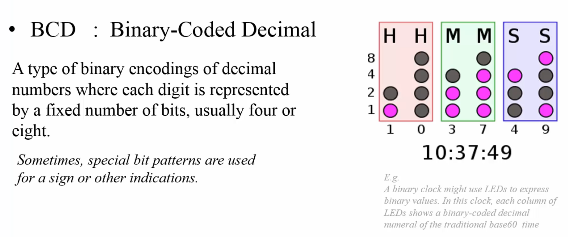
- Automatic management of 28-, 29- (leap year), 30-, and 31-day months.
- Daylight saving time adjustment programmable by software
RTC : Programmable Alarm
- The RTC provides two programmable alarms :
- Alarm A
- Alarm B
- We can set a time and date in the future for an alarm to occur, when the alarm occurs we can execute a block of code to perform a particular function we wish
RTC : Periodic auto-wakeup
- We can use this functionality to wake the device up from low power modes such as Sleep, Stop and Standby
RTC : Timestamp functionality
-
This functionality allows us to save the current date and time when a timestamp event occurs.
A timestamp event can be as simple as the press of a button
RTC : Tamper detection
-
Tamper detection allows us to know if our embedded device is being tampered with.
For example, in a consumer product if there is are particular part of the system that you feel its proprietary and you do not want anyone to be able to open that part and successfully analyze it, you can set a tamper detection so that as soon as someone tries to open that part it is detected and the appropriate action is taken (e.g. erasing the memory or self-destructing)
-
The RTC backup registers are not reset when the MCU reset, however, they are reset when a tamper detection event occurs.
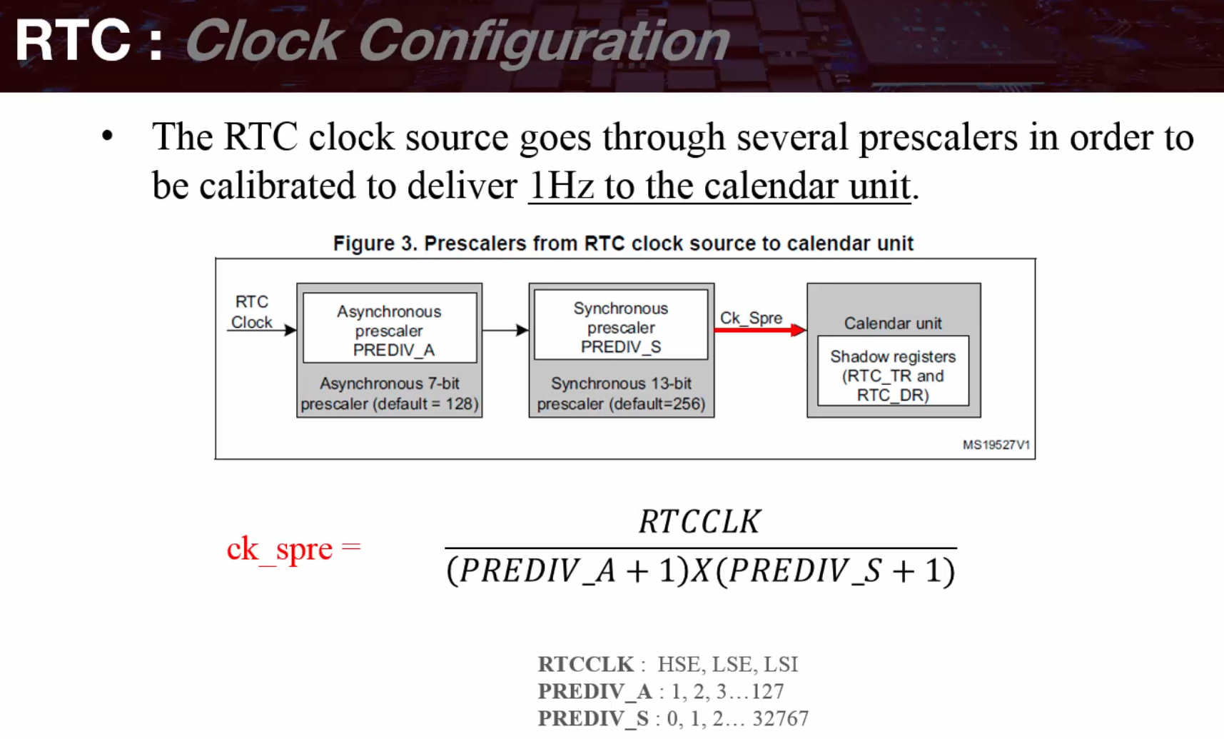
RTC : Clock Source
- Low Speed External (LSE)
- Low Speed Internal (LSI)
- High Speed External (HSE)
RTC Calendar
#define PWREN                 (1U<<28)
#define CR_DBP                (1U<<8)

#define CSR_LSION             (1U<<0)
#define CSR_LSIRDY            (1U<<1)

#define BDCR_BDRST            (1U<<16)
#define BDCR_RTCEN            (1U<<15)

/* Write protection keys */
#define RTC_WRITE_PROTECTION_ENABLE_1  ((uint8_t)0xCAU)
#define RTC_WRITE_PROTECTION_ENABLE_2  ((uint8_t)0x53U)

/* INIT / status flags */
#define RTC_INIT_MASK         0xFFFFFFFFU
#define ISR_INITF             (1U<<6)
#define ISR_RSF               (1U<<5)

/* Date/time helpers (BCD packed nibble masks in screenshots) */
#define WEEKDAY_FRIDAY        ((uint8_t)0x05U)
#define MONTH_DECEMBER        ((uint8_t)0x12U)
#define TIME_FORMAT_PM        (1U<<22)
#define CR_FMT                (1U<<6)

/* Prescaler values (from screenshots) */
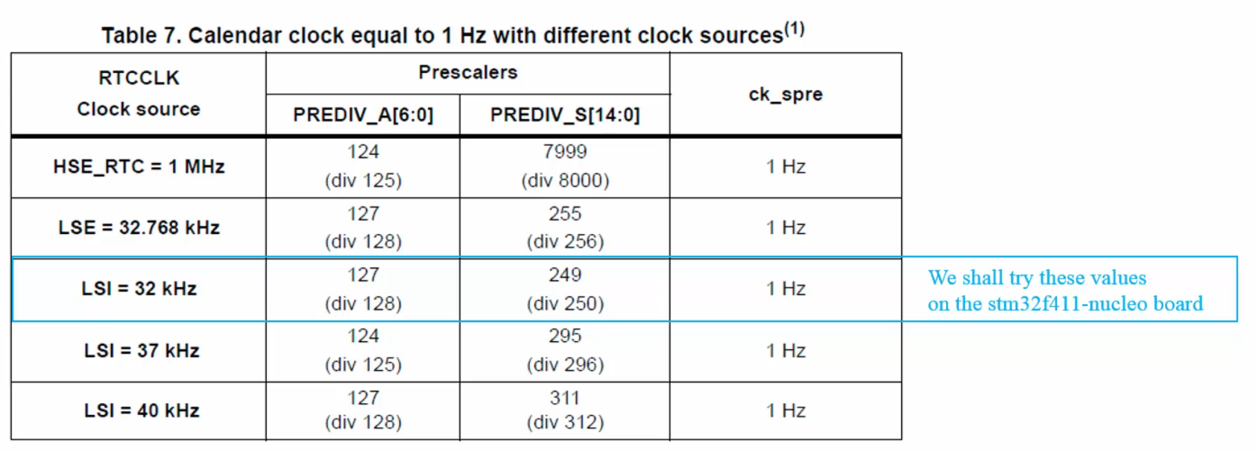
#define RTC_ASYNCH_PREDIV     ((uint32_t)0x7F)
#define RTC_SYNCH_PREDIV      ((uint32_t)0xF9)

/* ------------- Static helpers ------------- */
uint8_t rtc_convert_bin2bcd(uint8_t value)
{
    return (uint8_t)((((value) / 10U) << 4U) | ((value) % 10U));
}

uint8_t rtc_convert_bcd2bin(uint8_t value)
{
    return (uint8_t)(((uint8_t)((value) & (uint8_t)0xF0U) >> (uint8_t)0x4U) * 10U + ((value) & (uint8_t)0x0FU));
}

uint32_t rtc_date_get_day(void)
{
    return (uint32_t)((READ_BIT(RTC->DR, (RTC_DR_DT | RTC_DR_DU))) >> RTC_DR_DU_Pos);
}

uint32_t rtc_date_get_year(void)
{
    return (uint32_t)((READ_BIT(RTC->DR, (RTC_DR_YT | RTC_DR_YU))) >> RTC_DR_YU_Pos);
}

uint32_t rtc_date_get_month(void)
{
    return (uint32_t)((READ_BIT(RTC->DR, (RTC_DR_MT | RTC_DR_MU))) >> RTC_DR_MU_Pos);
}

uint32_t rtc_time_get_second(void)
{
    return (uint32_t)(READ_BIT(RTC->TR, (RTC_TR_ST | RTC_TR_SU)) >> RTC_TR_SU_Pos);
}

uint32_t rtc_time_get_minute(void)
{
    return (uint32_t)((READ_BIT(RTC->TR, (RTC_TR_MNT | RTC_TR_MNU))) >> RTC_TR_MNU_Pos);
}

uint32_t rtc_time_get_hour(void)
{
    return (uint32_t)((READ_BIT(RTC->TR, (RTC_TR_HT | RTC_TR_HU))) >> RTC_TR_HU_Pos);
}

static void rtc_set_asynch_prescaler(uint32_t AsynchPrescaler)
{
    MODIFY_REG(RTC->PRER, RTC_PRER_PREDIV_A, (AsynchPrescaler << RTC_PRER_PREDIV_A_Pos));
}

static void rtc_set_synch_prescaler(uint32_t SynchPrescaler)
{
    MODIFY_REG(RTC->PRER, RTC_PRER_PREDIV_S, (SynchPrescaler << RTC_PRER_PREDIV_S_Pos));
}

static void rtc_date_config(uint32_t WeekDay, uint32_t Day, uint32_t Month, uint32_t Year)
{
    register uint32_t temp = 0U;

    temp =  (WeekDay << RTC_DR_WDU_Pos)
          | (((Year  & 0xF0U) << (RTC_DR_YT_Pos - 4U)) | ((Year  & 0x0FU) << RTC_DR_YU_Pos))
          | (((Month & 0xF0U) << (RTC_DR_MT_Pos - 4U)) | ((Month & 0x0FU) << RTC_DR_MU_Pos))
          | (((Day   & 0xF0U) << (RTC_DR_DT_Pos - 4U)) | ((Day   & 0x0FU) << RTC_DR_DU_Pos));

    MODIFY_REG(RTC->DR,
               (RTC_DR_WDU | RTC_DR_MT | RTC_DR_MU | RTC_DR_DT | RTC_DR_DU | RTC_DR_YT | RTC_DR_YU),
               temp);
}

static void rtc_time_config(uint32_t Format12_24, uint32_t Hours, uint32_t Minutes, uint32_t Seconds)
{
    register uint32_t temp = 0U;

    temp =  Format12_24
          | (((Hours   & 0xF0U) << (RTC_TR_HT_Pos - 4U)) | ((Hours   & 0x0FU) << RTC_TR_HU_Pos))
          | (((Minutes & 0xF0U) << (RTC_TR_MNT_Pos - 4U)) | ((Minutes & 0x0FU) << RTC_TR_MNU_Pos))
          | (((Seconds & 0xF0U) << (RTC_TR_ST_Pos  - 4U)) | ((Seconds & 0x0FU) << RTC_TR_SU_Pos));

    MODIFY_REG(RTC->TR,
               (RTC_TR_PM | RTC_TR_HT | RTC_TR_HU | RTC_TR_MNT | RTC_TR_MNU | RTC_TR_ST | RTC_TR_SU),
               temp);
}

/* -------- Init mode control & flags -------- */
static void _rtc_enable_init_mode(void)
{
    RTC->ISR = RTC_INIT_MASK;
}

static void _rtc_disable_init_mode(void)
{
    RTC->ISR = ~RTC_INIT_MASK;
}

static uint8_t _rtc_isActiveflag_init(void)
{
    return ((RTC->ISR & ISR_INITF) == ISR_INITF);
}

static uint8_t _rtc_isActiveflag_rs(void)
{
    return ((RTC->ISR & ISR_RSF) == ISR_RSF);
}

static uint8_t rtc_init_seq(void)
{
    _rtc_enable_init_mode();
    while(_rtc_isActiveflag_init() != 1U) {}
    return 1U;
}

static uint8_t wait_for_synchro(void)
{
    /* Clear RSF */
    RTC->ISR &= ~ISR_RSF;
    /* Wait until registers synchronized */
    while(_rtc_isActiveflag_rs() != 1U) {}
    return 1U;
}

static uint8_t exit_init_seq(void)
{
    _rtc_disable_init_mode();
    return wait_for_synchro();
}

void rtc_init(void)
{
    /* Enable clock access to PWR */
    RCC->APB1ENR |= PWREN;

    /* Enable Backup access to config RTC */
    PWR->CR |= CR_DBP;

    /* Enable Low Speed Internal (LSI) */
    RCC->CSR |= CSR_LSION;

    /* Wait for LSI to be ready */
    while((RCC->CSR & CSR_LSIRDY) != CSR_LSIRDY) {}

    /* Force backup domain reset */
    RCC->BDCR |= BDCR_BDRST;

    /* Release backup domain reset */
    RCC->BDCR &= ~BDCR_BDRST;

    /* Set RTC clock source to LSI*/
    RCC->BDCR &= ~(1U<<8);
    RCC->BDCR |=  (1U<<9);

    /* Enable the RTC */
    RCC->BDCR |= BDCR_RTCEN;

    /* Disable RTC registers write protection */
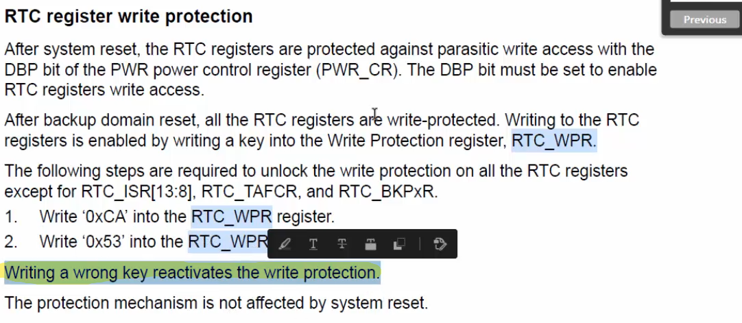
    RTC->WPR = RTC_WRITE_PROTECTION_ENABLE_1;
    RTC->WPR = RTC_WRITE_PROTECTION_ENABLE_2;

    /* Enter initialization mode */
    if(rtc_init_seq() != 1U)
    {
        /* Error handling placeholder */
    }

    /* Set desired date : Friday December 29th 2016 (BCD: 0x29 day, 0x16 year) */
    rtc_date_config(WEEKDAY_FRIDAY, 0x29U, MONTH_DECEMBER, 0x16U);

    /* Set desired time : 11:59:55 PM (BCD: 0x11 hour, 0x59 minute, 0x55 second) */
    rtc_time_config(TIME_FORMAT_PM, 0x11U, 0x59U, 0x55U);

    /* Set hour format */
    RTC->CR |= CR_FMT;

    /* Set Asynch prescaler */
    rtc_set_asynch_prescaler(RTC_ASYNCH_PREDIV);

    /* Set Synch prescaler */
    rtc_set_synch_prescaler(RTC_SYNCH_PREDIV);

    /* Exit the initialization mode */
    exit_init_seq();

    /* Re-enable (lock) RTC registers write protection (commonly 0xFF) */
    RTC->WPR = 0xFFU;
}

#include "stdio.h"

uint8_t time_buff[20] = {0};
uint8_t date_buff[20] = {0};

static void display_rtc_calendar(void)
{
    /* Display format :  hh : mm : ss */
    sprintf((char*)time_buff, "%.2d : %.2d : %.2d",
            rtc_convert_bcd2bin(rtc_time_get_hour()),
            rtc_convert_bcd2bin(rtc_time_get_minute()),
            rtc_convert_bcd2bin(rtc_time_get_second()));

    /* Display format :  mm : dd : yy */
    sprintf((char*)date_buff, "%.2d - %.2d - %.2d",
            rtc_convert_bcd2bin(rtc_date_get_month()),
            rtc_convert_bcd2bin(rtc_date_get_day()),
            rtc_convert_bcd2bin(rtc_date_get_year()));
}

int main(void)
{
    rtc_init();

    while(1)
    {
        display_rtc_calendar();
        for (int i =0; i < 330000; i++) {}
    }
}
RTC Alarm
RTC Timestamp
RTC Wakeup Timer
Standby and Wakeup
#define PWR_MODE_STANDBY        (PWR_CR_PDDS)
#define WK_PIN                  (1U<<0)

static void set_power_mode(uint32_t pwr_mode);

void wakeup_pin_init(void)
{
    //Enable clock for GPIOA
    RCC->AHB1ENR |= RCC_AHB1ENR_GPIOAEN;

    //Set PA0 as input pin
    GPIOA->MODER &= ~(1U<<0);
    GPIOA->MODER &= ~(1U<<1);

    //No pull
    GPIOA->PUPDR &= ~(1U<<0);
    GPIOA->PUPDR &= ~(1U<<1);
}

void standby_wakeup_pin_setup(void)
{
    /*Wait for wakeup pin to be released*/
    while(get_wakeup_pin_state() == 0){}

    /*Disable wakeup pin*/
    PWR->CSR &= ~(1U<<8);

    /*Clear all wakeup flags*/
    PWR->CR |= (1U<<2);

    /*Enable wakeup pin*/
    PWR->CSR |= (1U<<8);

    /*Enter StandBy mode*/
    set_power_mode(PWR_MODE_STANDBY);

    /*Set SLEEPDEEP bit in the CortexM System Control Register*/
    SCB->SCR |= (1U<<2);

    /*Wait for interrupt*/
    __WFI();
}

void get_wakeup_pin_state(void)
{
    return ((GPIOA->IDR & WK_PIN) == WK_PIN);
}

static void set_power_mode(uint32_t pwr_mode)
{
    MODIFY_REG(PWR->CR,
               (PWR_CR_PDDS | PWR_CR_LPDS | PWR_CR_FPDS | PWR_CR_LPLVDS | PWR_CR_MRLVDS),
               pwr_mode);
}

// ...main.c

uint8_t g_btn_press;
static void check_reset_source(void);
void clock_config(void);
static void led_blink_forever(void);

/*Press the blue push-button to enter StandBy mode*/
/**@note: PA0 is wakeup pin and it is active low
 * connect a jumper wire from PA0 to ground in normal mode,
 * pull out jumper wire and connect it to 3.3v to cause a change in logic which will
 * in turn trigger the WAKEUP**/

int main(void)
{
    uart2_tx_init();
    wakeup_pin_init();
    check_reset_source();
    gpio_interrupt_init(); // init the button interrupt
    led_init();

    led_blink_forever();
    while(1)
    {
    }
}

static void led_blink_forever(void)
{
    while(1)
    {
        GPIOA->ODR ^= (1U << 5);
        for(int i = 0; i < 90000; i++){}
    }
}

static void check_reset_source(void)
{
    /*Enable clock access to PWR*/
    RCC->APB1ENR |= RCC_APB1ENR_PWREN;

    if ((PWR->CSR & PWR_CSR_SBF) == (PWR_CSR_SBF))
    {
        /*Clear Standby flag*/
        PWR->CR |= PWR_CR_CSBF;

        led_blink();
        printf("System resume from Standby.....\n\r");

        /*Wait for wakeup pin to be released*/
        while (get_wakeup_pin_state() == 0) {}
    }

    /*Check and Clear Wakeup flag*/
    if ((PWR->CSR & PWR_CSR_WUF) == PWR_CSR_WUF)
    {
        PWR->CR |= PWR_CR_CWUF;
    }
}

static void btn_callback(void)
{
    standby_wakeup_pin_setup();
}

void EXTI15_10_IRQHandler(void)
{
    if ((EXTI->PR & EXTI_IMR_IM13) == (EXTI_IMR_IM13))
    {
        /*Clear EXTI flag*/
        EXTI->PR = EXTI_IMR_IM13;

        //Do something...
        btn_callback();
    }
}