building process, memory and Linker script
Memory Model
- Flash Memory :
- Read-Only
- Begins at address 0x08000000
- Size depends on specific STM32 microcontroller
- Program code is stored here.
- Contains a vector table at address 0x08000004This consists of pointers to the various exception handlers
- SRAM :
- Read and Write
- Begins at 0x20000000
- Size depends on specific STM32 microcontroller
- Variables and Stack are stored here
Linker Script
- Script given to the linker in order to specify the memory layout and to initialize the various memory sections used by the firmware.
- The linker script is responsible for making sure various portions of the firmware are in their proper place and also for associating meaningful labels with specific regions of memory used by the startup code.
The script has 4 features:
- Memory Layout : Available memory types
- Section Definitions : Placing specific parts at specific locations
- Options : Commands e.g. ENTRY POINT
- Symbols : Variables to inject into program at link time
Memory
- In order to allocate program memory, the linker needs to know the types of memory, their addresses and sizes.
- We use the MEMORY definition to provide this information.
MEMORY
{
    name [(attr)] : ORIGIN = origin, LENGTH = len
    …
}
E.g.
MEMORY
{
    FLASH(rx) : ORIGIN = 0x08000000, LENGTH = 512K
    SRAM(rwx) : ORIGIN = 0x20000000, LENGTH = 128K
}
Sections
- Code and data are organized into sections.
- Symbols of the same memory region are placed in the same section.
SECTIONS
{
    …
}
E.g.
SECTIONS
{
    .text :
    {
        *(.text)   /* merge all .text sections of input files */
    }> FLASH
}
Sections (cont.)
The 3 relevant sections:
- .text Placed in the FLASH
- .data Placed in the SRAM
- .bss Placed in the SRAM
Startup Code
Contains:
- Reset Handler
- This function copies the initial values for variables from the FLASH where the linker places them to the SRAM.
- It also zeros out the uninitialized data portion of the SRAM.
- Interrupt Vector Table
- This is an array that holds memory address of interrupt handler functions
- In order to allow application code to conveniently redefine the various interrupt handlers, every required vector is assigned an overrideable _weak alias to a default function which loops forever
VMA and LMA
-
LMA : Load Memory Address
The address at which a section is loaded
-
VMA : Virtual Memory Address
The address of a section during execution
-
The linker distinguishes between the VMA and LMA address
Getting familiar with the script (cont.)
- Every allocatable and loadable output section has two addresses: VMA and LMA
- The VMA (Virtual Memory Address) is the address the section will have when the output file is run.
- The LMA (Load Memory Address) is the address at which the section is loaded.
- In most cases the LMA and VMA are the same.
Except in the case where the data section is loaded into FLASH and then copied to RAM when the firmware starts. - Each section in an object file has a name and size
- A section may be marked as loadable
This means the content should be loaded to memory when the output file is run - A section with no content is marked as allocatable
This means some area of memory should be set aside, but nothing in particular should be loaded there. - A section which is neither loadable nor allocatable often contains some sort of debugging information.
commands
- ENTRY: Sets program entry address
- MEMORY: Describes the locations and sizes of the different memories available
- ALIGN: Inserts padding to align location
- SECTIONS: Used to map input sections to output sections and describes how to place output sections in memory.
- KEEP: Tells linker to keep the specified section even if no symbols in that section are referenced
- AT >: This is a directive; it tells the linker to load a section’s data to somewhere other than the address it is located at.
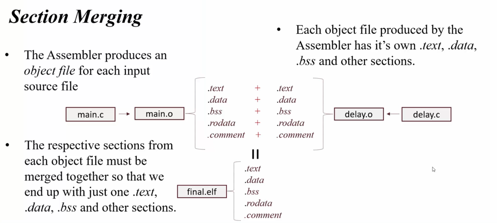
Section Merging
example
/* Memories definition */
MEMORY
{
  RAM    (xrw)    : ORIGIN = 0x20000000,   LENGTH = 128K
  FLASH    (rx)    : ORIGIN = 0x8000000,   LENGTH = 512K
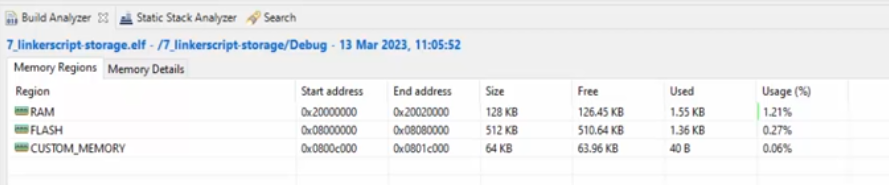
  CUSTOM_MEMORY (rx) : ORIGIN = 0x800C000,	LENGTH = 64K
}

/* Sections */
SECTIONS
{
  /* The startup code into "FLASH" Rom type memory */
  .isr_vector :
  {
    . = ALIGN(4);
    KEEP(*(.isr_vector)) /* Startup code */
    . = ALIGN(4);
  } >FLASH

   /*Create this section in the RAM*/
   .custom_ram_block 0x20000100(NOLOAD) :
   {

   /*Keep variables even if they are not referenced*/
    KEEP(*(.custom_ram_block))
   }>RAM

   .custom_flash_block 0x08004000 :
   {
   	KEEP(*(.custom_flash_block))
   }>FLASH

  .custom_section :
	 {
	 	KEEP(*(.custom_section))
	 } >CUSTOM_MEMORY
#define CUSTOM_FUNC  __attribute__((section(".custom_section")))
#define RAM_FUNC  __attribute__((section(".RamFunc")))

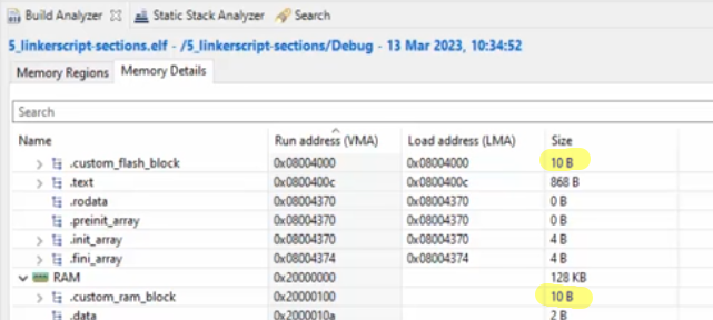
unsigned char __attribute__((section(".custom_ram_block"))) custom_ram_buff[10];   //10 bytes
unsigned char __attribute__((section(".custom_flash_block"))) custom_flash_buff[10];   //10 bytes

void RAM_FUNC _led_toggle(uint32_t dly_ms)
{
	GPIOA->ODR ^= LED_PIN;
    delay(dly_ms);
}

void CUSTOM_FUNC _led_toggle2(uint32_t dly_ms)
{
	GPIOA->ODR ^= LED_PIN;
    delay(dly_ms);
}