Interrupts
Interrupts : Interrupt vs. Polling
int main()
{
    while(1){
        . . .
    }
}

OnSwitch_ISR{
    getData()
}
Interrupt
int main()
{
    while(1){
        if(switch = on ){
            getData();
        }
        . . .
    }
}
Polling
Interrupts NVIC
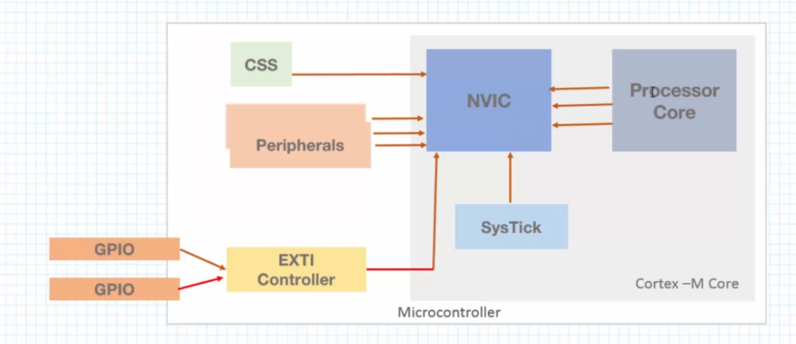
- Interrupts from the processor core are know as exceptions.
- Interrupts from outside the processor core are known as hardware exceptions or Interrupt Requests.
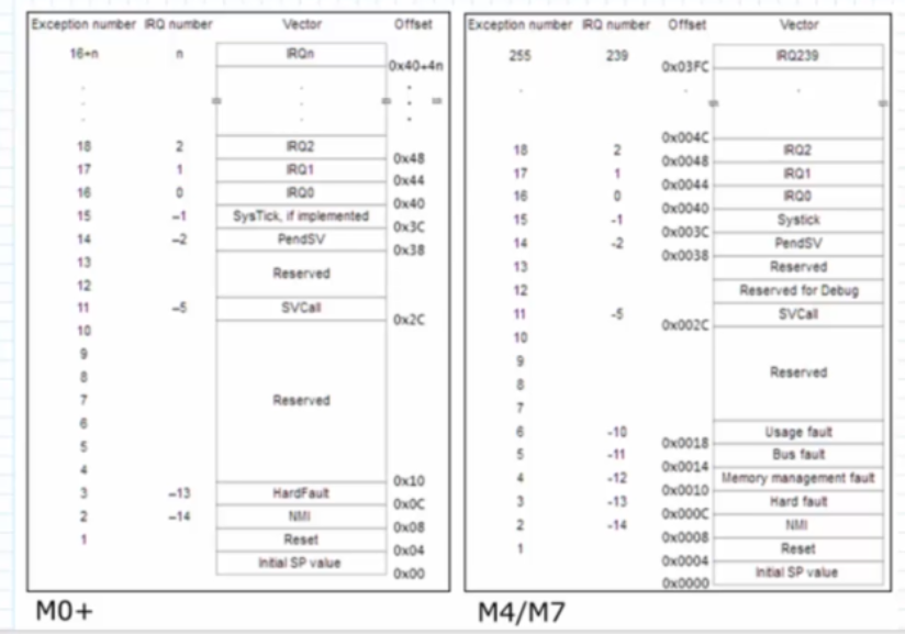
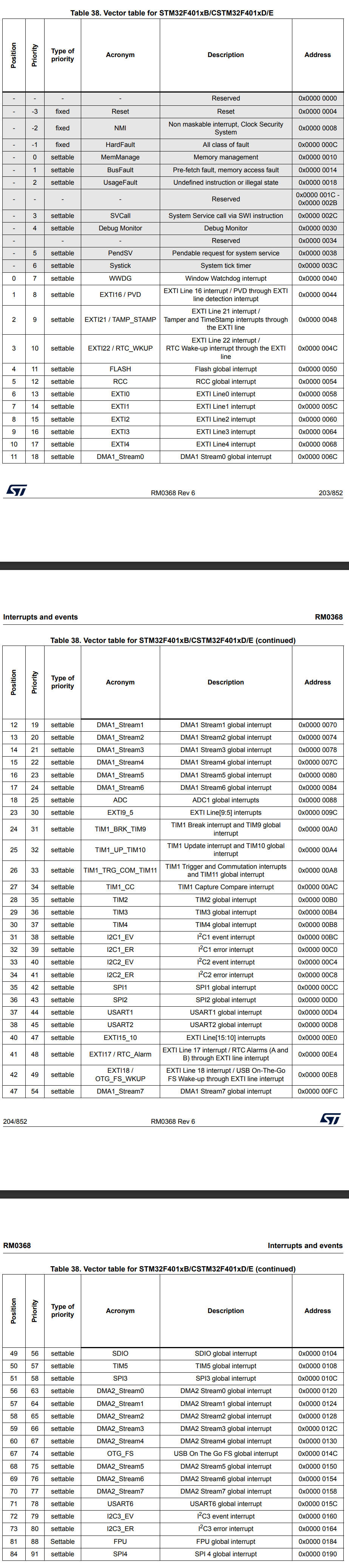
Interrupts: The Vector Table
The vector table contains the addresses of the Interrupt Handlers and Exception Handlers.
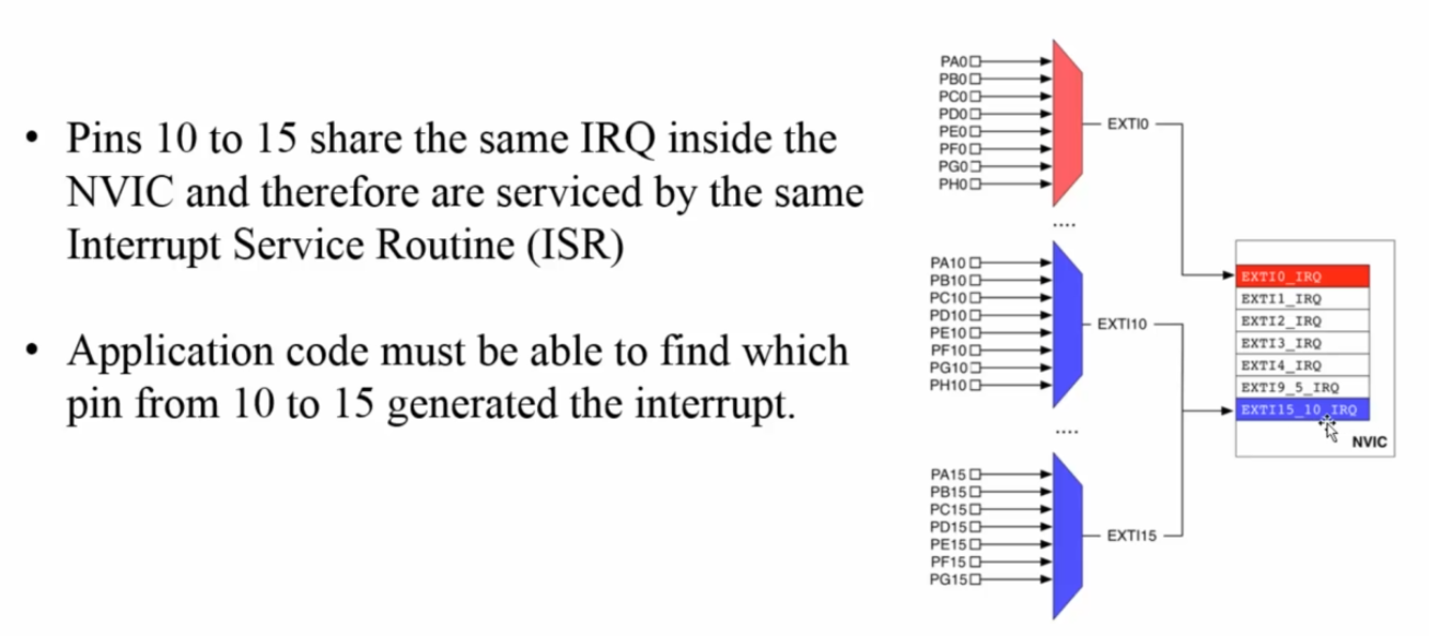
Interrupts: External Interrupt (EXTI) Lines
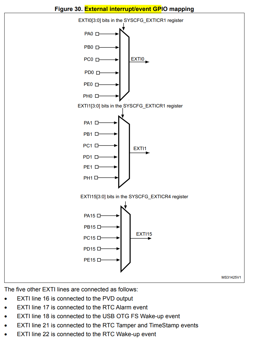
- GPIO pins are connected to EXTI lines
- It possible to enable interrupt for any GPIO pin
- Multiple pins share the same EXTI line
- Pin 0 of every Port is connected EXTI0_IRQ
- Pin 1 of every Port is connected EXTI1_IRQ
- Pin 2 of every Port is connected EXTI2_IRQ
- Pin 3 of every Port is connected EXTI3_IRQ
...
This means we cannot have PB0 and PA0 as input interrupt pins at the same time since they are connected to the same multiplexer i.e. EXTI0
Same for PC4 and PB4 at the same time, etc.
Interrupts : States
- Disabled : This is the default state
- Enabled : Interrupt is enabled
- Pending : Waiting to be serviced
- Active : Being serviced
example:
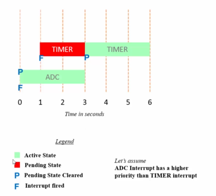
ADC Interrupt fires at time t = 0.
This is indicated by F
Since there is no other interrupt, the pending state is cleared and the interrupt becomes active.
This is indicated by P
At time t=1 TIMER interrupt fires
This is indicated by F
Since it has a lower priority than the ADC interrupt it remains in the pending state
At time t=3 ADC interrupt completes its execution
Since there is no other interrupt with a higher priority, the pending state of the TIMER interrupt is cleared and the interrupt becomes active.
This is indicated by P
Interrupts : Priorities
Some interrupt priorities are defined by ARM, these cannot be changed. E.g.:
- RESET : Priority of -3
- NMI : Priority of -2
- HardFault : Priority of -1
Lower number = Higher priority
Interrupts : Priorities in M3/M4/M7
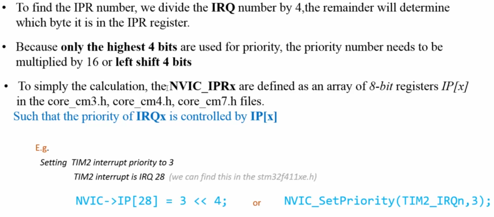
- Priority of each interrupt is defined using one of the Interrupt Priority Registers (IPR)
- Each Interrupt Request (IRQ) uses 8-bits inside a single IPR register
- Therefore one IPR register allows us to configure the priorities of four different Interrupt Requests
- Example: IPR0 holds the priorities of IRQ0, IRQ1, IRQ2 and IRQ3
- There are 60 Interrupt Priority Registers: IPR0 – IPR59
- There are 60 x 4 = 240 Interrupt Requests (IRQ)
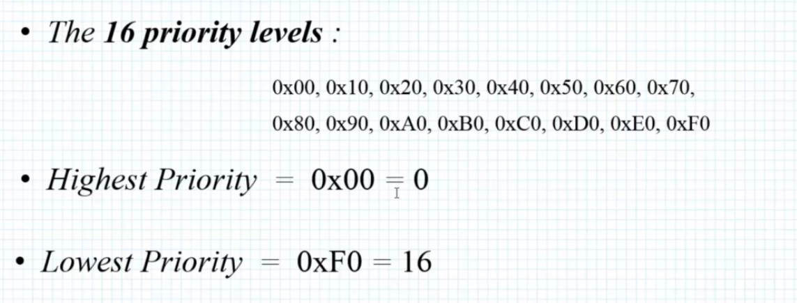
💡 - 8-bits to configure the priority of an IRQ implies there are 2⁸ = 255 priority levels
- STM32 microcontrollers use only the 4 upper bits to configure the priority of each IRQ. This implies that in STM32 MCUs there are 2⁴ = 16 priority levels
- IPRn = IRQ(4n+3), IRQ(4n+2), IRQ(4n+1) and IRQ(4n)
Interrupts : Sub-priorities
- The Interrupt Priority Registers (IPR) can also be divided into sub-priorities
- In this configuration there are a series of bits defining preemption priority and a series of bits defining the sub-priority
- The sub-priority will determine which IRQ will be executed first in the case of multiple pending IRQs
GPIO Interrupt example
#include "stm32f4xx.h"

#define GPIOCEN    (1U<<2)
#define SYSCFGEN   (1U<<14)
#define LINE13     (1U<<13)

void pc13_exti_init(void)
{
    /*Disable global interrupts (recommended)*/
    __disable_irq();

    /*Enable clock access for GPIOC*/
    RCC->AHB1ENR |= GPIOCEN;

    /*Set PC13 as input*/
    GPIOC->MODER &= ~(1U<<26);
    GPIOC->MODER &= ~(1U<<27);

    /*Enable clock access to SYSCFG*/
    RCC->APB2ENR |= SYSCFGEN;

    /*Select PORTC for EXTI13*/
    SYSCFG->EXTICR[3] |= (1U<<5); //  PC[x] pin

    /*Unmask EXTI13*/
    EXTI->IMR |= (1U<<13);

    /*Select falling edge trigger*/
    EXTI->FTSR |= (1U<<13);

    /*Enable EXTI13 line in NVIC*/
    NVIC_EnableIRQ(EXTI15_10_IRQn);  // EXTI15_10_IRQn=40

    /*Enable global interrupts*/
    __enable_irq();
}

static void doStuff()
{
...
}

/* Intr routine */
void EXTI15_10_IRQHandler(void)
{
	// check which pin trigred the intr
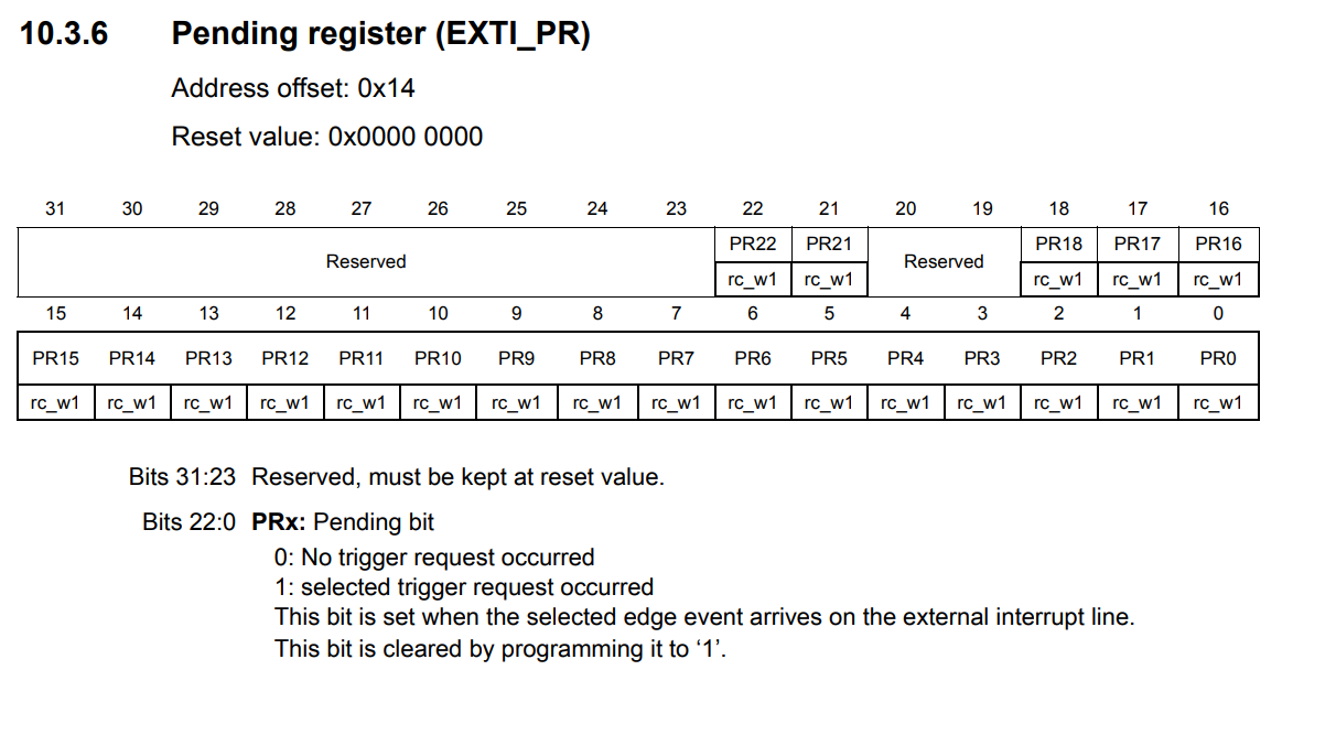
	if ((EXTI->PR & LINE13) != 0)
	{
		//Cleat PR flag
		EXTI->PR != LINE13;

		doStuff();
	}
}
💡 SYSCFG stands for System Configuration Controller. It is a peripheral in STM32 microcontrollers that manages system-level features, including external interrupt line mapping.
Why enable SYSCFG?
You need to enable the SYSCFG clock because the EXTI (external interrupt) configuration registers are part of the SYSCFG peripheral. Without enabling its clock, you cannot configure which GPIO port is connected to an EXTI line (like mapping PC13 to EXTI13). This is done by setting the appropriate bit in RCC->APB2ENR.
💡