WatchDog
A watchdog timer is a hardware timer that resets the system if the software fails to operate correctly. It helps recover from software faults by restarting the microcontroller when the timer is not periodically cleared by the running program. This ensures the system continues to function even if it gets stuck or crashes.
A watchdog timer works by counting down from a preset value. If the timer reaches zero, it triggers a system reset. The running program (usually the main loop or a critical task) must periodically reset or "kick" the watchdog timer before it expires. This is done by writing a specific value to a watchdog control register. If the program hangs or gets stuck, it fails to reset the timer, causing the watchdog to reset the system and restore normal operation.
No, the watchdog timer is not enabled by default on most microcontrollers, including STM32. You must explicitly configure and enable it in your code if you want to use it.
Watchdogs: Introduction
- Watchdogs are timers which are used to reset the microcontroller when a problem occurs.
- In the STM32 microcontroller there are two watchdogs
- Independent Watchdog (IWDG)
- Windowed Watchdog (WWDG)
- Watchdogs are used to detect and resolve malfunctions due to software failure, and to trigger system reset or an interrupt (window watchdog only) when their counter reaches a given timeout value.
IWDG
- The Independent Watchdog (IWDG) is completely separate from the main STM32 system.
- It is located within the backup power domain
- It is clocked by its own dedicated low-speed clock (LSI) and thus stays active even if the main clock fails.
- The IWDG is best suited to applications which require the watchdog to run as a totally independent process outside the main application, but have lower timing accuracy constraints
IWDG: Main Features
- Free running 12-bit downcounter.
- Clocked from its own oscillator and therefore can run in Standby Mode and Stop Mode
- The STM32 system resets automatically when the downcounter value reaches 0x000
Timeout Values
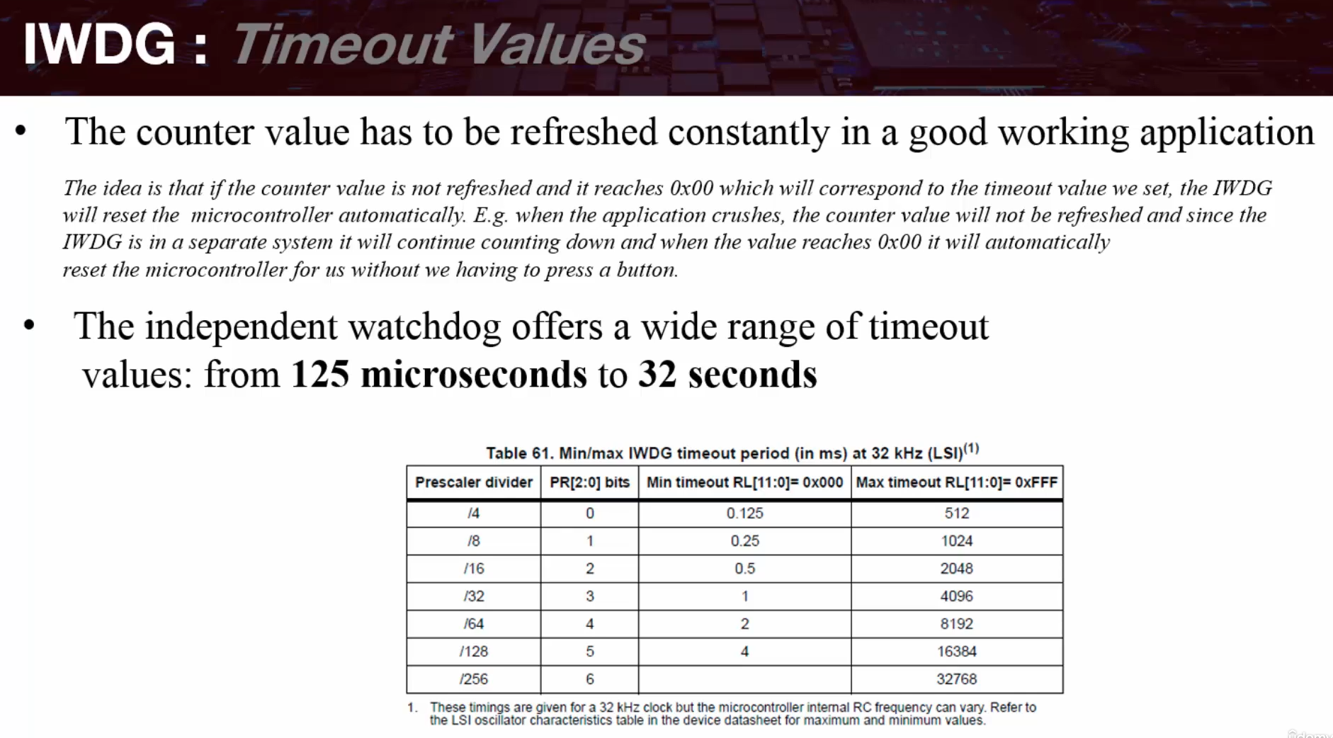
IWDG: Timeout Values
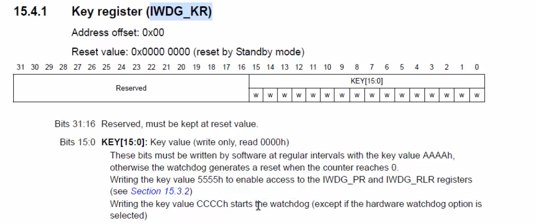
- IWDG is started by writing 0xCCCC in the Key register (IWDG_KR)
When this happens the counter starts counting down from a reset value of 0xFFF - When the key value 0xAAAA is written in the Key register, the Reload register (IWDG_RLR) value is reloaded in the counter and the system reset is prevented.
IWDG: Hardware Watchdog
- If the “Hardware watchdog” feature is enabled (through the device option bits), the watchdog is automatically enabled at power-on, and will generate a reset unless the Key register is written by the software before the counter reaches end of count.
IWDG: Register Access and Protection
- Write access to the IWDG Prescaler (IWDG_PR) and Reload (IWDG_RLR) registers is protected. To modify these registers we must write the code 0x5555 in the IWDG Key register (IWDG_KR) register.
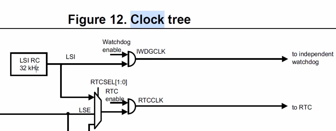
IWDG
#define IWDG_KEY_ENABLE             0x0000CCCU
#define IWDG_KEY_WR_ACCESS_ENABLE   0x00005555U
#define IWDG_PRESCALER_4            0x00000000U
#define IWDG_RELOAD_VAL             0xFFF
#define IWDG_KEY_RELOAD             0x0000AAAAU

static uint8_t isIwdg_ready(void);

void iwdg_init(void)
{
    /*Enable the IWDG by writing 0x0000CCCC in the IWDG_KR register*/
    IWDG->KR = IWDG_KEY_ENABLE;

    /*Enable register access by writing 0x0000 5555 in the IWDG_KR register*/
    IWDG->KR = IWDG_KEY_WR_ACCESS_ENABLE;

    /*Set the IWDG Prescaler*/
    IWDG->PR  = IWDG_PRESCALER_4;

    /*Set the reload register (IWDG_RLR) to the largest value 0xFFF*/
    IWDG->RLR = IWDG_RELOAD_VAL;

    /*Wait for the registers to be updated (IWDG_SR = 0x0000 0000)*/
    while (isIwdg_ready() != 1) {}

    /*Refresh the counter value with IWDG_KR (IWDG_KR = 0x0000 AAAA)*/
    IWDG->KR = IWDG_KEY_RELOAD;
}

static uint8_t isIwdg_ready(void)
{
    return ((READ_BIT(IWDG->SR, IWDG_SR_PVU | IWDG_SR_RVU) == 0U) ? 1UL : 0UL);
}

// ...main.c
uint8_t g_btn_press;

int main(void)
{
    uart2_tx_init();
    gpio_interrupt_init(); // init button interrupt
    led_init();
    check_reset_source();
    iwdg_init();
    while(1)
    {
        if( g_btn_press != 1 )
        {
            /*Refresh IWDG down-counter to default value*/
            IWDG->KR = IWDG_KEY_RELOAD;
            led_blink();
        }
    }
}

static void check_reset_source(void)
{
    if ((RCC->CSR & RCC_CSR_IWDGRSTF) == (RCC_CSR_IWDGRSTF))
    {
        /*Clear IWDG Reset flag*/
        RCC->CSR = RCC_CSR_RMVF;

        /*Turn LED On*/
        led_on();
        printf("RESET was caused by IWDG.....\n\r");

        while( g_btn_press != 1 )
        {
        }

        g_btn_press = 0;
    }
}

static void btn_callback(void)
{
    g_btn_press = 1;
}

void EXTI15_10_IRQHandler(void)
{
    if((EXTI->PR & EXTI_IMR_IM13) == (EXTI_IMR_IM13))
    {
        /*Clear EXTI flag*/
        EXTI->PR = EXTI_IMR_IM13;

        //Do something...
        btn_callback();
    }
}
WWDG
WWDG: Introduction
• Watchdogs are used to detect software faults
• The window watchdog has a programmable free-running downcounter that must be refreshed within a window period that guarantees proper software execution.
• If a system fault occurs and the programmed time period expires, the window watchdog generates a system reset.
• The window watchdog can be used to detect abnormally late or early behaviors of the firmware.
• The WWDG is best suited for applications which are required to react within an accurate timing window.
• An Early Wakeup Interrupt (EWI) can be generated before a reset happens, this can be used to manage certain actions before a system reset.
WWDG: Main Feature
• Programmable free-running downcounter
• Conditional Reset
- Reset occurs when the downcounter value becomes less than 0x40
- Reset occurs if the downcounter is reloaded outside the window
• Early wakeup interrupt (EWI) - Triggered (if enabled) when the downcounter is equal to 0x40
- Can be used to save context before reset
- Can be used to reload the downcounter
WWDG: How it works
• PCLK1 is the clock source for the WWDG
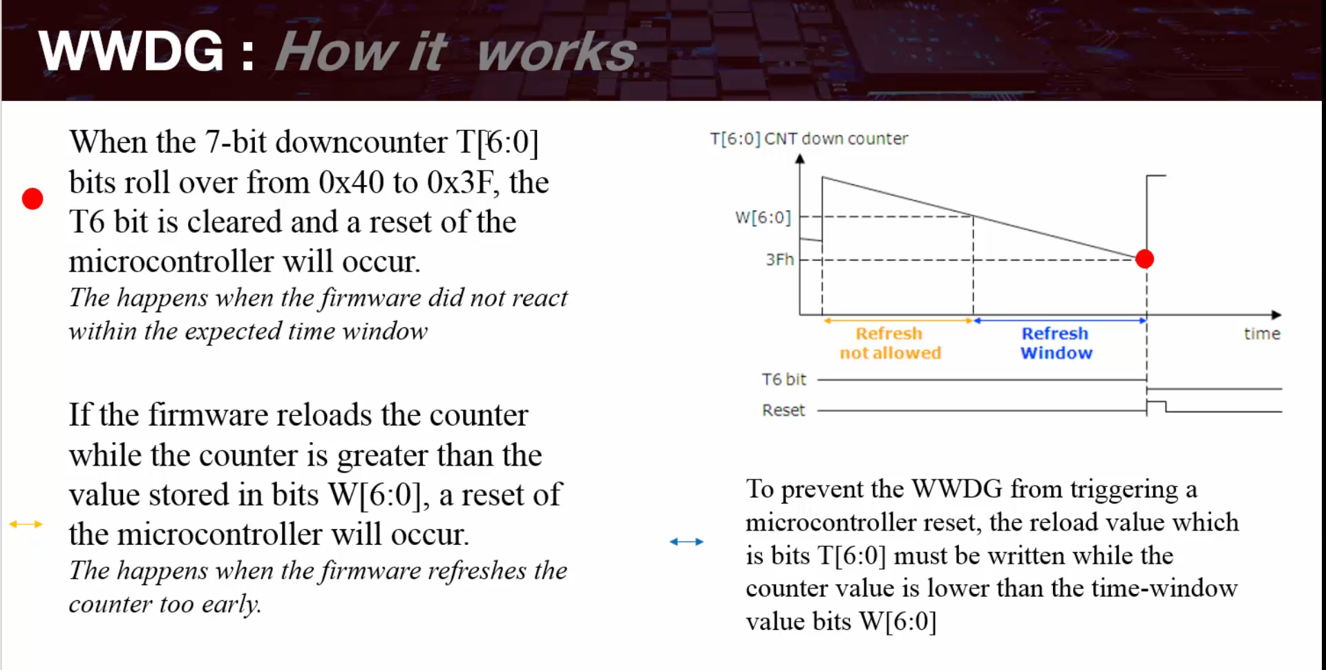
• Bits T[6:0] of the watchdog control register (WWDG_CR) counts down until they roll over from 0x40 to 0x3F, when this happens a reset is generated.
• Bits W[6:0] of the watchdog configuration register (WWDG_CFR) contains the window value
• Bits T[6:0] and W[6:0] are compared in order to evaluate the time to refresh the downcounter in the configuration windows
• If the downcounter is reloaded too early or too late, the WWDG will reset the microcontroller
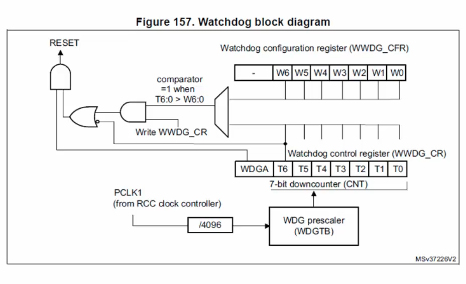
WWDG: Clock Source
• PCLK1 = APB1 Clock
WWDG: Settings
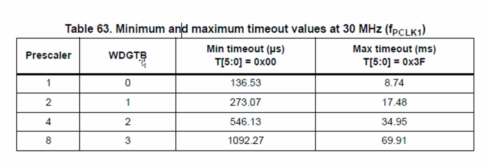
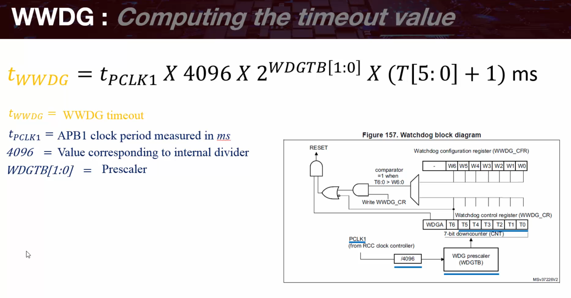
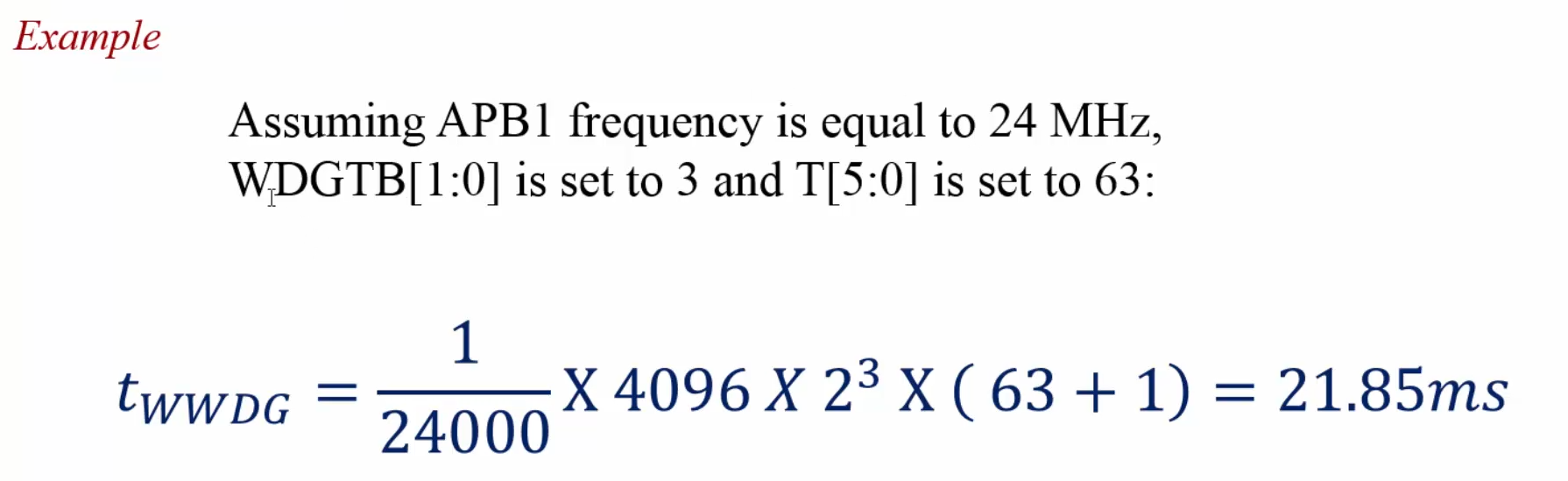
The WWDG time base is pre-scaled from PCLK1 clock
There is a 4096 internal divider and 4 pre-dividers: 1, 2, 4 or 8 selectable by the WWDG configuration register (WWDG_CFR)
WWDG: Source of Reset
• Once the WWDG generates a reset, a status flag called WWDGRSTF is set in the RCC_CSR register identifying the source of the reset.
WWDG: Early Wakeup Interrupt (EWI)
• The EWI interrupt occurs when the downcounter value reaches 0x40
• The EWI interrupt is enabled by setting the EWI bit in the WWDG configuration register (WWDG_CFR)
• The EWI interrupt is cleared by writing “0” to the EWIF bit in the WWDG status register (WWDG_SR).
void wwdg_init(void)
{
    /*Enable the peripheral clock WWDG*/
    RCC->APB1ENR |= RCC_APB1ENR_WWDGEN;

    /*Set prescaler to have a rollover each about ~2s*/
    WWDG->CFR |= (1U<<7);
    WWDG->CFR |= (1U<<8);

    /*Set window value to same value (~2s) as downcounter
      in order to be able to refresh the WWDG almost immediately*/
    WWDG->CFR &= ~WWDG_CFR_W;
    WWDG->CFR |= 0x7E;

    /*Set counter*/
    WWDG->CR &= ~WWDG_CR_T;
    WWDG->CR |= 0x7E;

    /*Enable WWDG*/
    WWDG->CR |= WWDG_CR_WDGA;
}

/**
 * @brief  System Clock Configuration
 * The system Clock is configured as follow :
 * System Clock source        = HSE
 * SYSCLK(Hz)                 = 8000000
 * HCLK(Hz)                   = 2000000
 * AHB Prescaler              = 4
 * APB1 Prescaler             = 1
 * APB2 Prescaler             = 1
 * HSE Frequency(Hz)          = 8000000
 * VDD(V)                     = 3.3
 * Main regulator output voltage = Scale1 mode
 * Flash Latency(WS)          = 0
 *
 * @param  None
 * @retval None
 */
void clock_config(void)
{
    /* Enable HSE oscillator */
    RCC->CR |= RCC_CR_HSEBYP;
    RCC->CR |= RCC_CR_HSEON;

    /*Wait till HSERDY goes LOW*/
    while((RCC->CR & RCC_CR_HSERDY) == (RCC_CR_HSERDY)){}

    /* Set FLASH latency */
    FLASH->ACR &= ~FLASH_ACR_LATENCY;
    FLASH->ACR |= FLASH_ACR_LATENCY_0WS;

    /* Sysclk activation on the main PLL */
    RCC->CFGR &= ~RCC_CFGR_HPRE;
    RCC->CFGR |= RCC_CFGR_HPRE_DIV4;

    /*Set clock source*/
    RCC->CFGR &= ~RCC_CFGR_SW;
    RCC->CFGR |= RCC_CFGR_SW_HSE;

    /*Wait till HSE is used as system clock*/
    while((RCC->CFGR & RCC_CFGR_SWS) != RCC_CFGR_SWS_HSE){}

    /* Set APB1 prescaler */
    RCC->CFGR &= ~RCC_CFGR_PPRE1;
    RCC->CFGR |= RCC_CFGR_PPRE1_DIV1;

    /* Set APB2 prescaler */
    RCC->CFGR &= ~RCC_CFGR_PPRE2;
    RCC->CFGR |= RCC_CFGR_PPRE2_DIV1;
}