ADC analog-to-digital converter
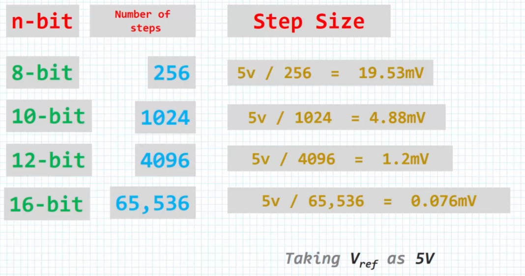
ADC Independent Modes
- Single-channel, single conversion mode
- Multichannel(scan), single conversion mode
- Single-channel continuous conversion mode
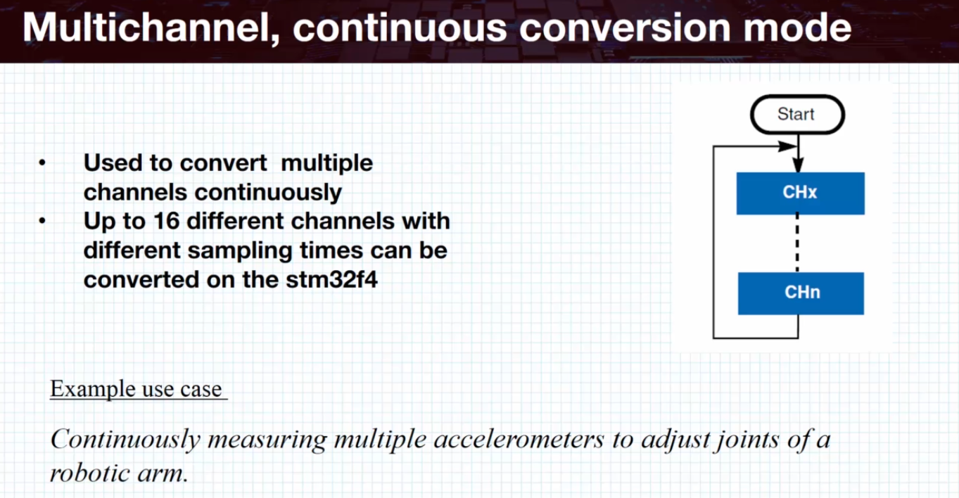
- Multichannel continuous conversion mode
- Injected continuous conversion mode
💡 An ADC module has 16 channels
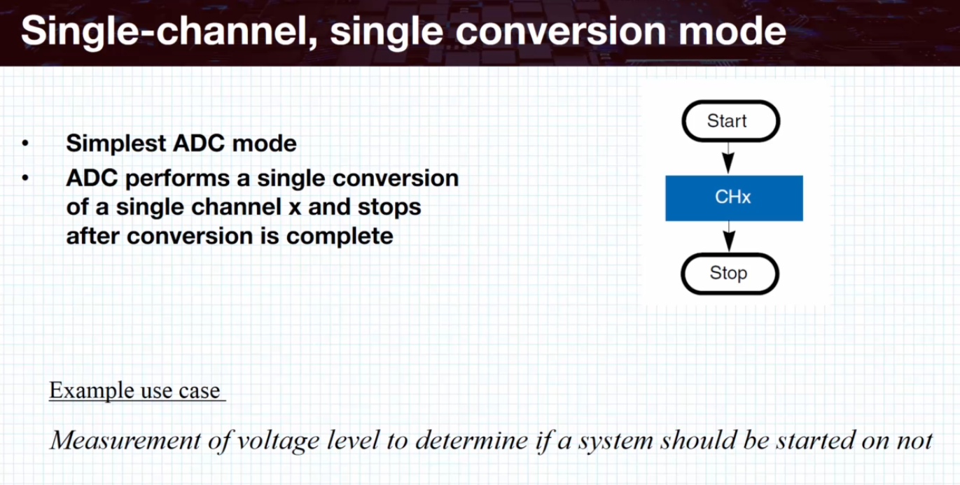
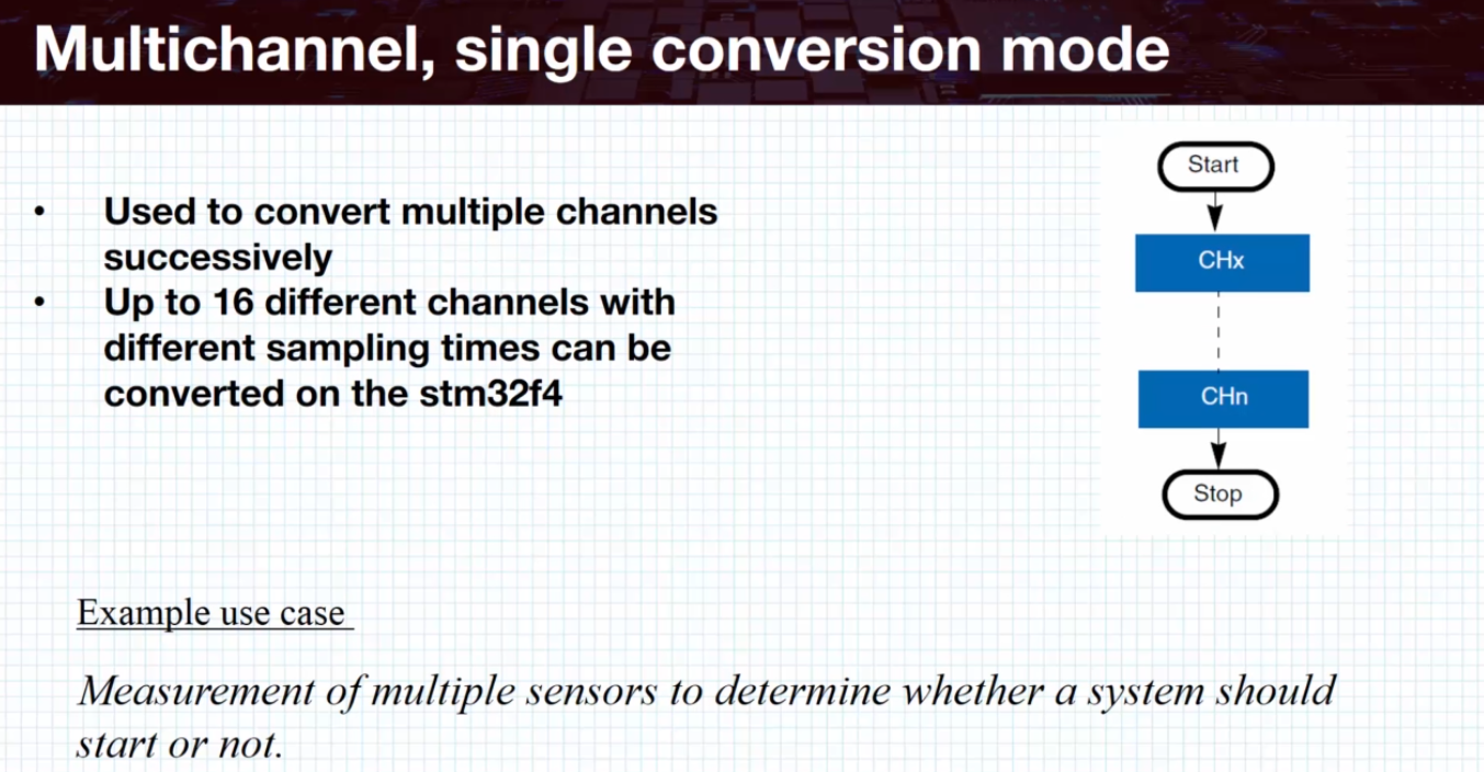
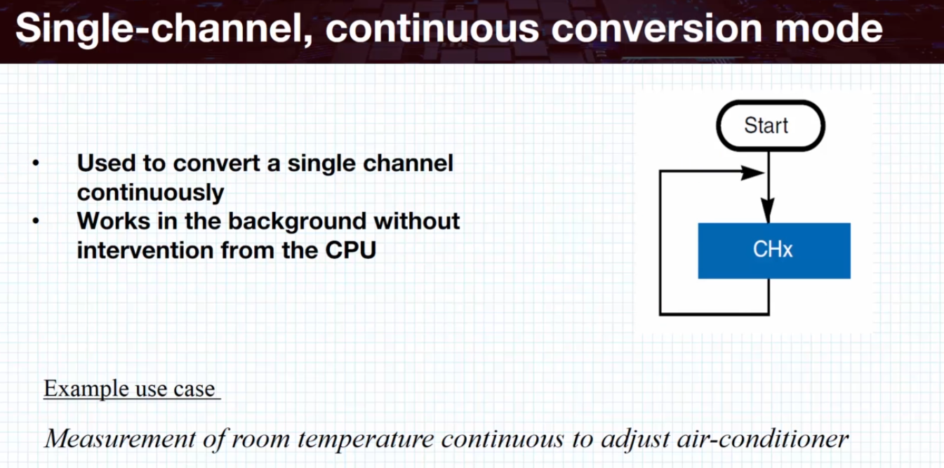
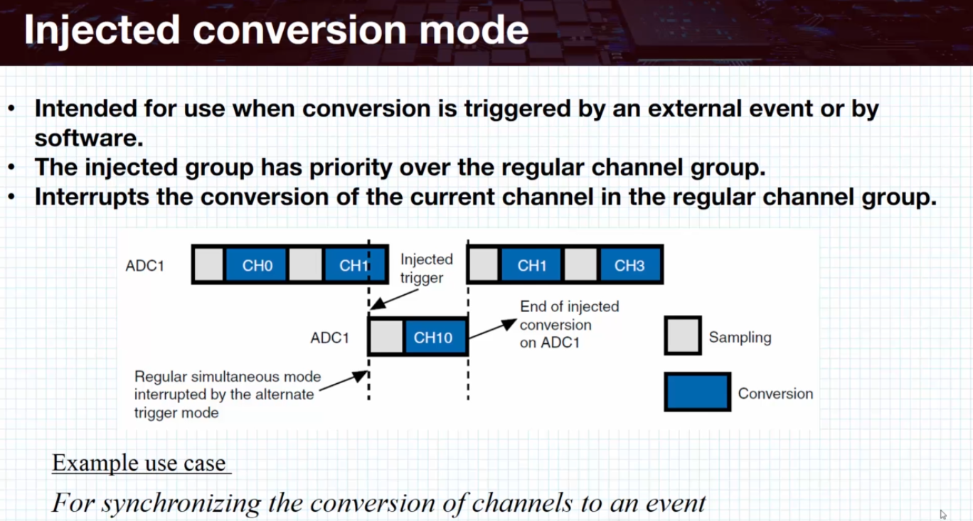
injected conversion mode gives some channels a higher priority then other channels
#include "stdint.h"
#include "stm32f4xx.h"

#define GPIOAEN         (1U<<0)
#define ADC1EN          (1U<<8)
#define ADC_CH1         (1U<<0)
#define ADC_SEQ_LEN_1   0x00
#define CR2_ADON        (1U<<0)
#define CR2_SWSTART     (1U<<30)
#define SR_EOC          (1U<<1)

void pal_adc_init(void)
{
    /***Configure the ADC GPIO pin ***/
    //Enable clock access to GPIOA
    RCC->AHB1ENR |= GPIOAEN;

    //Set the mode of PA1 to analog
    GPIOA->MODER |= (1U<<2);
    GPIOA->MODER |= (1U<<3);

    /***Configure the ADC module***/
    //Enable clock access to ADC
    RCC->APB2ENR |= ADC1EN;

    //Conversion sequence start
    ADC1->SQR3 = ADC_CH1;

    //Conversion sequence length
    ADC1->SQR1 = ADC_SEQ_LEN_1;

    //Enable ADC module
    ADC1->CR2 |= CR2_ADON;
}

void start_conversion(void)
{
    //Start adc conversion
    ADC1->CR2 |= CR2_SWSTART;
}

uint32_t adc_read(void)
{
    //Wait for conversion to be complete
    while(!(ADC1->SR & SR_EOC)){}

    //Read converted result
    return (ADC1->DR);
}

int main(void)
{
    pal_adc_init();

    while(1)
    {
        start_conversion(); // Single-channel, single conversion mode
        // you have to start conversion when you need it

        uint32_t sensor_value = adc_read();
    }
}
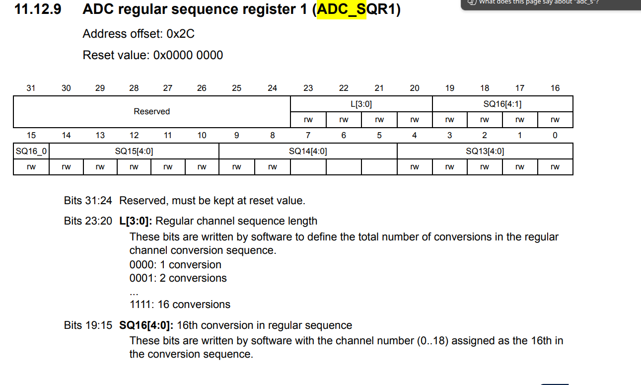
💡 In STM32 microcontrollers, the sequence length in the ADC (Analog-to-Digital Converter) module refers to the number of channels that will be converted in a single ADC conversion sequence.
When using the ADC in scan mode, you can configure it to sample multiple analog input channels one after another. The sequence length determines how many channels are included in this sequence. For example, if the sequence length is set to 3, the ADC will convert three different channels in order during each sequence.
- The sequence length is set in the ADC_SQR1 register (for most STM32 series).
- Each channel in the sequence is configured in the ADC_SQRx registers (SQR1, SQR2, SQR3).
Example:
If you want to sample channels 1, 5, and 7 in one sequence, you set the sequence length to 3 and configure the sequence registers accordingly.
Summary:
- Sequence length = Number of channels to convert per ADC sequence.
- Used in scan mode for multi-channel sampling.
- Configured in ADC registers (usually SQR1).
#define CR2_CONT   (1U<<1)

void start_conversion(void)
{
		// Enable continuous conversion
		ADC1->CR2 |= CR2_CONT;

    //Start adc conversion
    ADC1->CR2 |= CR2_SWSTART;
}

int main(void)
{
    pal_adc_init();
    start_conversion();

    while(1)
    {

        uint32_t sensor_value = adc_read();
    }
}
ADC interrupt example
#define CR1_EOCIE  (1U<<5)

void pal_adc_inter_init(void)
{
    /***Configure the ADC GPIO pin ***/
    //Enable clock access to GPIOA
    RCC->AHB1ENR |= GPIOAEN;

    //Set the mode of PA1 to analog
    GPIOA->MODER |= (1U<<2);
    GPIOA->MODER |= (1U<<3);

    /***Configure the ADC module***/
    //Enable clock access to ADC
    RCC->APB2ENR |= ADC1EN;

    // enable end of conversion interrupt
    ADC1->CR1 |= CR1_EOCIE;
    NVIC_EnableIRQ(ADC_IRQn);

    //Conversion sequence start
    ADC1->SQR3 = ADC_CH1;

    //Conversion sequence length
    ADC1->SQR1 = ADC_SEQ_LEN_1;

    //Enable ADC module
    ADC1->CR2 |= CR2_ADON;
}

void ADC_IRQHandler(void)
{
	if ((ADC1->SR & SR_EOC) != 0)
	{
		// clear EOC
		ADC1->SR &= ~SR_EOC;

		// do stuff
	}
}